The Fuselage (Page 5 of 5)
Journal Cover Page Page 1 Page 2 Page 3 Page 4
(To navigate the photo journal, click on the tabs on the right and the links at the top or bottom of this page.)
Wrapping Up |
|
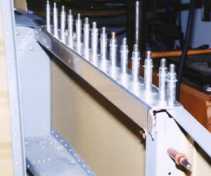 |
A few more items and it will be time for the finishing kit. Here the canopy deck is cut and clecoed in place. |
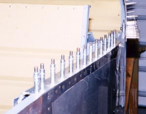 |
Outside view shows the canopy deck trimmed to match the curve of the fuselage skin. |
 |
|
| Here is the interface between the forward and aft canopy decks. | |
 |
The instrument sub-panel is pretty flimsy. Its necessary to clamp a rigid straight edge to keep it lined up for drilling the overlap between the two sub-panel halves. |
 |
|
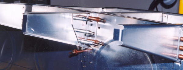
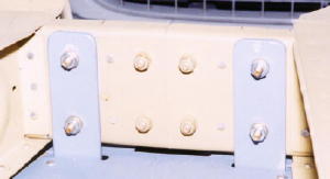
| Junction of instrument sub-panel and rib with reinforcing plate in place. | |
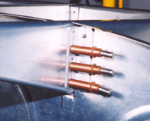 |
This is the support angle where sub-panel meets outer rib. Right side shown. |
 |
|
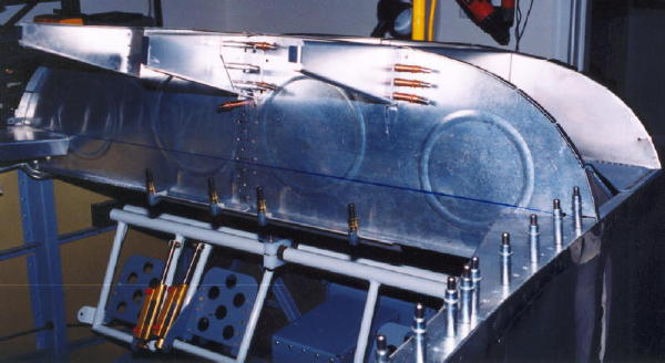
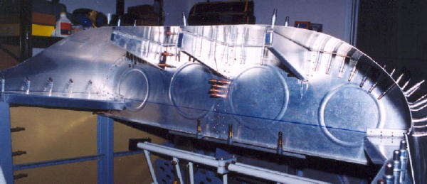
| Zooming out you can see whole instrument sub-panel. The blue horizontal line marks the bend line. Sub-panel bends back slightly along this line to be perpendicular to the sloping forward top skin. | |
 |
|
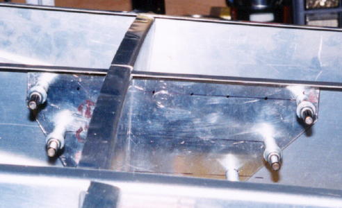
| Viewing from the right side, here is the reinforcing plate on the center forward rib. | |
 |
|
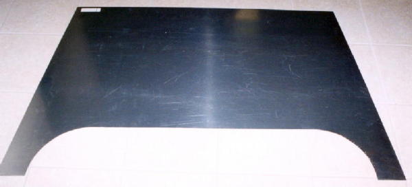
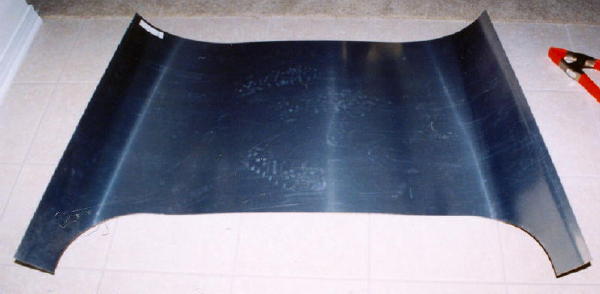
| The forward top skin trimmed and ready to be bent to fit the fuselage. | |
 |
|
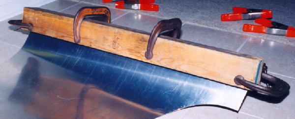
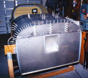
| Here is my highly technical bending method. Yes its 2/4's and C-clamps. Works pretty well, if you put your weight into it. | |
 |
|
| The finished product. Still requires a little force to lay down on the side skin, but better not press my luck trying to bend the edge any more aggressively. | |
 |
Top skin is in place and drilled to the forward structure. |
 |
|
| Looking forward at the forward structure. Looks like this plane needs an instrument panel. | |
 |
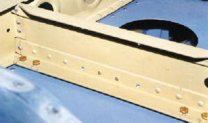
The horizontal stabilizer rear spar is drilled and bolted to fuselage. |
 |
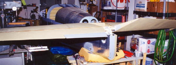
This is the front spar of the horizontal stabilizer. It's bolted down to the aft deck. |
 |
|
| Here you can see the small space of the one-car garage that is my workshop these days. | |
 |
|
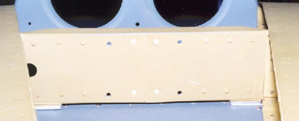
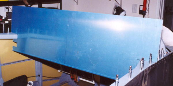
| Looking forward at the horizontal stabilizer front spar, you can see the spacers under the front spar. These are needed to make the horizontal stabilizer cord line level with the main longerons. | |
 |
|
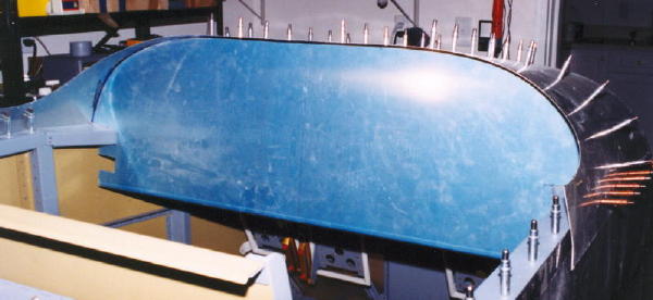
| Here is the instrument panel blank. Its been notched around the forward canopy deck and is ready to be trimmed to fit under the top forward skin. | |
| Looking from the right side, you can see the how the instrument panel mates with the forward structure. | 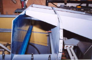 |
 |
|
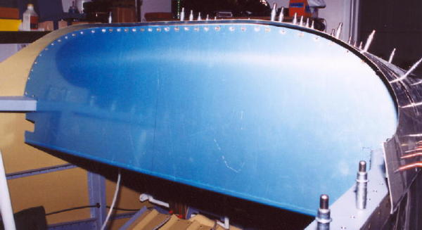
| Now, the instrument panel has been trimmed and fits well under the forward top skin. | |
 |
|
| There is a reinforcing angle riveted to the top skin. The instrument panel blank has to be drilled to it. The holes along the top edge of the instrument panel as seen here are countersunk for flat head screws that go into plate nuts attached to the support angle. | |
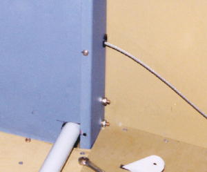
| Digressing a bit, I went back to cut the holes in the side baggage panels for the flap control rod. | 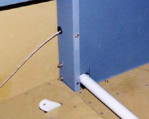 |
 |
And, here is the left side panel. |
| The flap control rod is in place and connected to the electric flap motor. | 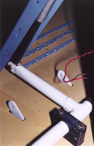 |
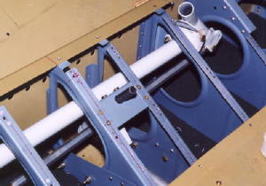 |
The manual aileron trim mechanism is mounted between the two most inboard ribs in the seat area just aft of the wing spar. |
| Here is another shot of the elevator bell crank access whole, on the right side, without the cover plate installed. | 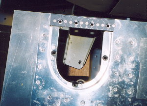 |
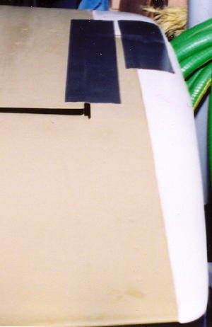 |
I used duct tape to fix the elevators in the neutral position in preparation for rigging the verticle stabilizer and drilling it to the fuselage. |
 |
|
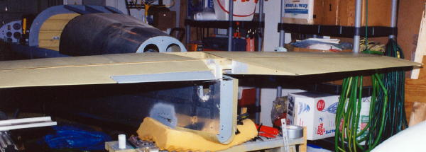
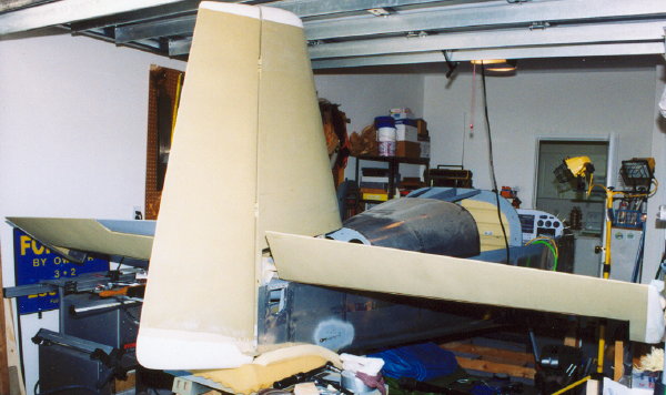
| Here is the elevator and horizontal stabilizer in position in position fitting the verticle stabilizer. | |
 |
|
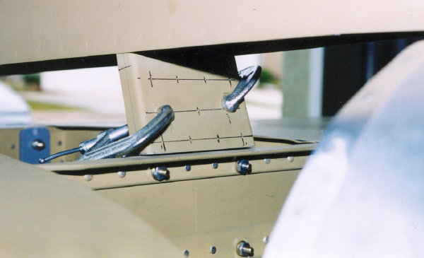
| The verticle stabilizer affixes to the fuselage by way of the bracket shown here. You can see three of the four bolts holding the bracket to the fuselage and the clamps that hold the verticle stabilizer. | |
 |
|
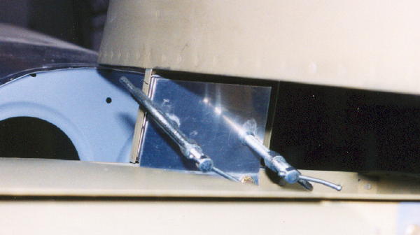
| Here is a view of the clamps from the backside. | |
| This is the lower rudder pivot bracket. For the rudder to track properly, it has to be poslitioned vertically below the upper bracket. I'm using dental floss and a lead fishing weight as a plumb bob right in the bracket hinge holes. | 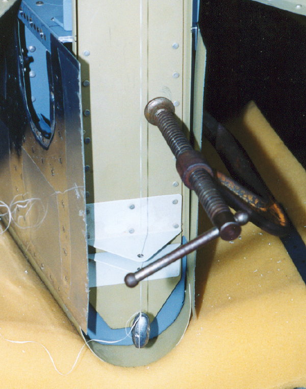 |
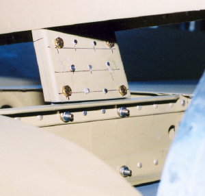 |
I had to shim the vertical stabilizer forward attach so much that bolts were required in place of the four corner rivets for strength. |
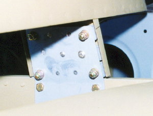 |
Here is the backside. |
 |
|
| Sure is a small one-car garage. | |
| Here is the rudder control stop fabricated and riveting to the fuselage. | 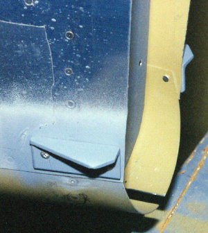 |
 |
|
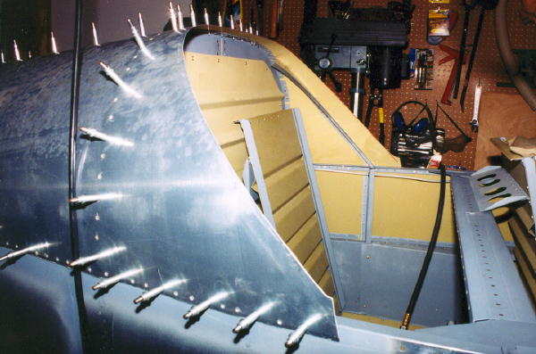
| The aft top skin or turtle deck is now ready for riveting. Just need to get someone willing to come over and help out for a couple of hours. | |
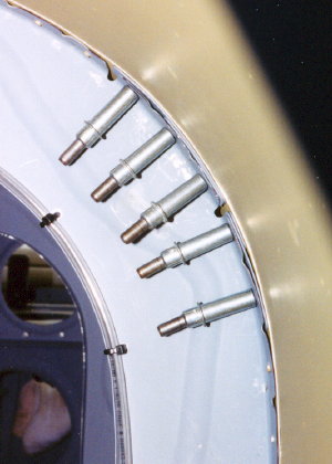 |
Well, almost ready. The flat flanges on the bulkheads did not fit the skin curve very well. This area required a lot of shimming and the skin still did not fair well. You really can't tell how badly it will fair until you try to rivet it. Then comes the drilling out rivets, shimming, and reriveting. I won't tell you how many times. |
| RV-6 builder, Cliff Nunnery, did the honors. For some reason, he preferred that I lay inside the tail cone and do the bucking while he riveted. | 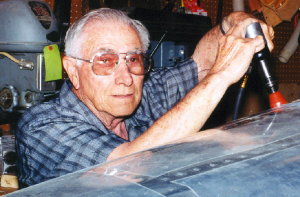 |
 |
I think that I saved this section for riveting later, but now I can't remember why. |
| A picture from the standing in the kitchen. A few of the items are already hanging on the firewall. | 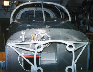 |
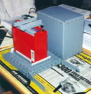 |
I'm not sure why this picture is out of sequence, but there is a lot of jumping around from this point on. The battery box inside the cockpit is modified to accept the smller 17 amp-hr battery and keep it firmly in place. |