The Fuselage (Page 2 of 5)
Journal Cover Page Page 1 Page 3 Page 4 Page 5
(To navigate the photo journal, click on the tabs on the right and the links at the top or bottom of this page.)
Jigging The Fuselage |
|
| The plans come with a drawing from which the fuselage jig is built. It is recommended that you borrow one if possible. The only one I found close by was in use by another builder. So, I just followed the drawing. With the materials in hand, it took a couple of days to complete. I'm not sure what all the fuss is about. It seemed to go pretty smoothly for me. This picture shows how I used lag screws to join on the support legs to the horizontal rails. All the joints also, have liquid nails for good measure. | 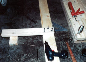 |
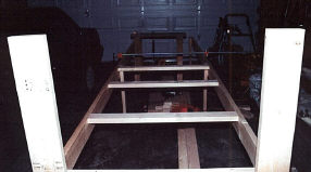 |
Its coming together so quickly that I forget to take pictures until it's almost halfway finished. The set of pipe clamps I have for woodworking are very useful in holding it in position until I can drill and screw in the lag bolts. |
| Just pausing to savor the moment. | 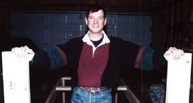 |
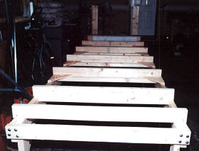 |
Here you can see the fuselage jig pretty much finished. All that is left is some diagonal leg braces and the vertical support for the aft-most bulkhead. |
| The firewall is mounted to the jig in this picture. Its actually just resting on it here. It will be bolted to the up-rights after its all leveled and re-leveled. The garage floor is very uneven, so I got some of those height adjustable feet. That made it a lot easier. | 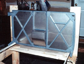 |
 |
|
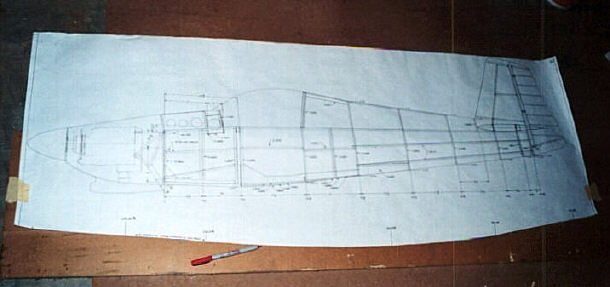
| After the firewall, the next part that goes on the jig is the main longerons. They run the whole length of the fuselage from the firewall to the last bulkhead on the tail. The longerons have to be bent to match the curve of the plane's body. To do this, we will need a template. That is the subject of this picture. One of the drawings has a line drawn on it that corresponds to this curve. Here, I've cut it out and positioned it on a piece of plywood that will become a template for checking the bending progress. | |
| The longeron bending operation requires a bench vise bolted to a pretty hefty work bench. With both longerons in the vise, they are separated from each other with the angle and symmetry checked and re-checked. This bend allows each longeron to angle down from the wing spar bulkhead to the firewall. To make the curve that allows the longerons to follow the skin, each is progressively bent with a series of small bends. This is a trial and error affair consisting of many iterations of bending, laying on the floor to check against the template, more bending, more checking, and so on. One other thing that must be done along the way is to take out the twist that forms as the longerons are bent. | 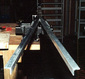 |
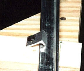 |
When the longerons are finally bent to the builder's satisfaction, the lay flat on the jig except for the part that angles to the firewall brackets. Their placement on the jig is critical. Each must be an equal distance from the centerline drawn on the jig and the exact distance apart at each bulkhead station. Once they are positioned, the longerons can be clamped down with the homemade clamp shown in this picture. |
| Next, the longerons need to be clamped to the firewall brackets to prepare for drilling. | 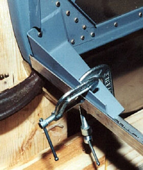 |
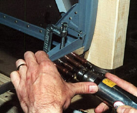 |
Here, I'm drilling the longerons to the steel firewall brackets. |
| The first bulkhead that is positioned on the longerons is the F604 Bulkhead that will eventually receive the wing spars. This shot shows the small piece of channel that will secure it to the longeron. | 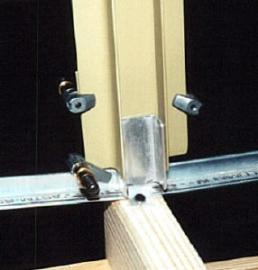 |
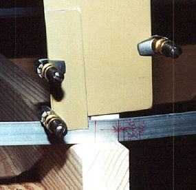 |
This is the outboard view. The tilt of the bulkhead to the longeron is another critical parameter. It will determine the angle of incidence of the wings, a fundamental aerodynamic characteristic of the plane. In other words, screw it up and you won't fly far. I'm using a small scrap of aluminum to help align the bulkhead side with the longeron side so the skin will lie flat. |
| I clamped a couple of strips of wood from the firewall to the F604 Bulkhead to keep it at the right angle during the fitting and drilling process. | 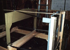 |
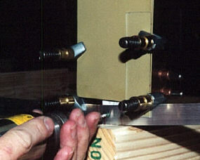 |
OK, its at the perfect angle and its time to drill. |
| At the bottom (top as the structure is upside down in the jig) of the fuselage, there is a short longeron between the firewall and the F604 Bulkhead. Here, it is being fitted to the firewall bracket. | 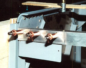 |
| And, here it is clecoed to the Bulkhead after drilling. The X's mark a section that needs to be trimmed away to clear the landing gear mount. | 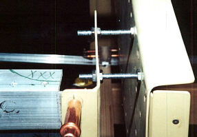 |
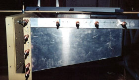 |
Zooming out a little bit, you can see the plate that reinforces this area to deal with the stresses that will be imposed by the landing gear bracket. |
| Here is a shot of the reinforcing plate at the lower longeron and firewall junction. This plate requires a slight S-bend to fit properly. It will help spread the load caused by the engine bolts that tie the engine mount to the fuselage. | 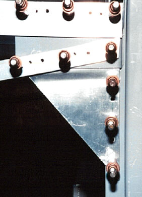 |
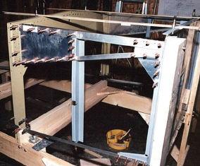 |
Zooming out again, you can see the whole assembly between the firewall on the right and the wing attach bulkhead on the left. |
| The part that is still missing in the picture above is this small longeron. Shown here is where it attaches to the wing attach bulkhead. It's necessary to do a little trimming and fitting including putting the "joggle" in the end. | 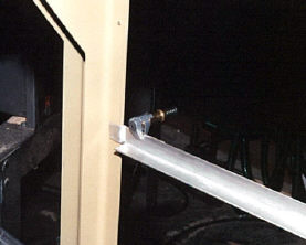 |
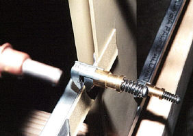 |
Here is the same picture as above but from the outside. A scrape of aluminum keeps the angle flush with the bulkhead while it is drilled so the side skin will lie flat when it is eventually put in place. |
| This interestingly shaped part will end up at the top of the seat back bulkhead. It's shape depends on the type of canopy you chose. This one is cut to shape for the sliding canopy. | 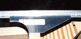 |
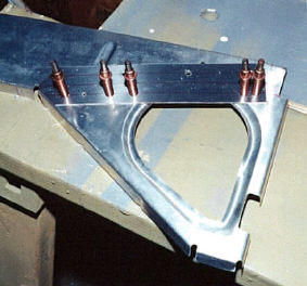 |
Here I'm laying out the splice plate that goes on the two inner most seat ribs. You have to cut the rib and then add this splice plate so that the top portion of the ribs are removable providing access to the control column. |
| Here the seat ribs which go between the wing attach bulkhead on the right and the seat back bulkhead on the left are being fitted and drilled. | 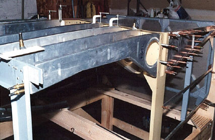 |
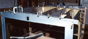 |
Here is a rear view of the seat back bulkhead with the seat ribs clamped into place for drilling. |
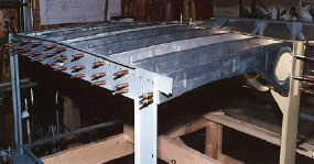 |
Same as above, but after drilling the seat ribs. |
| Here is a shot of the bottom of the arm rest which goes between the wing attach bulkhead and the seat back bulkhead. It's been fitted and drilled. | 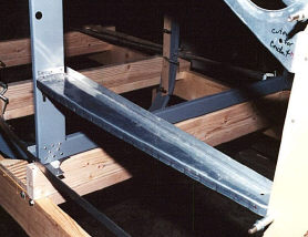 |
| Zooming in, you can see the small bracket that will hold the arm rest to the seat back bulkhead. | 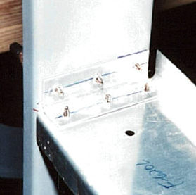 |
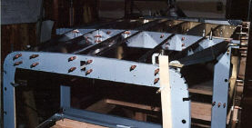 |
Here is a view of the bulkheads and ribs clamped in place looking forward. The rear of the baggage bulkhead is in the foreground. The stick is clamped to the bulkhead as a temporary brace to help keep it relatively straight. |
| From the side, you can see one of the problems I encountered with the baggage bulkhead. Where the triangular shaped rib meets the baggage bulkhead, your supposed to attach the rib to the bulkhead flange. The problem is that the bulkhead flange is notched at this location. My solution was to cut a small piece of scrap as a splice that is tack riveted to both the rib and one of the bulkhead flange tabs. The small C-clamps in the picture are holding the rib in place flush with the neighboring rib. | 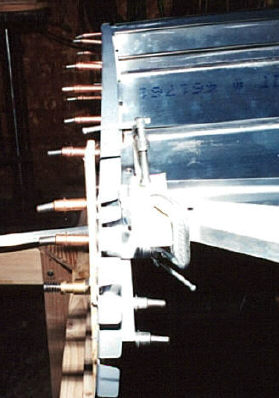 |
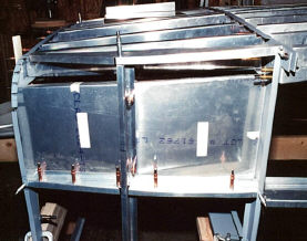 |
Here is a shot of the lower baggage compartment side walls viewed from the outside. These inner walls will protect the rudder cables which run behind them. |
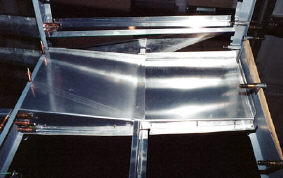 |
This is what they look like from the inside looking up. The aft one, on the right, is riveted in place and the forward one, on the left, will be screwed in place so that it is removable for rudder cable inspection. |
| These short 2x4s clamped together is the bending brake I used to bend the two lower baggage side panels so they meet will meet up with the baggage floor ribs. The picture isn't very good, but you can just see the shiny aluminum sticking out of the front of the brake. | 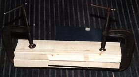 |
| Using another 2x4 and a hammer, I bent the protruding edge of metal to form the lower flange on the panel. | 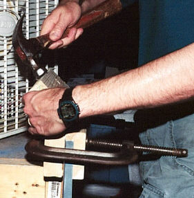 |
| Here is the 'after' picture that shows the flange bent at a right angle to the panel held by the brake. | 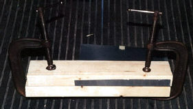 |
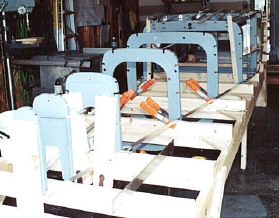 |
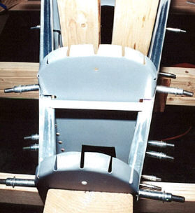
The rest of the bulkheads go in pretty quickly. They are all clamped to the jig and positioned on the main longerons. |
| At this point, I must pause to thank one of my helpers. Charlie keeps me company through the slow process of building the fuselage. | 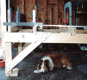 |
 |
Here is a shot of the last two bulkheads in the tail, F612 & F611. You can see that they have already been drilled to the J-stringers. |
| The F610 bulkhead didn't fit quite right. So, I moved it forward about 1/2 inch. I used a plywood spacer and a couple of 2x4s as a jig extension to position them correctly. Now they fit perfectly between the longeron and J-stringers without pushing them out any. | 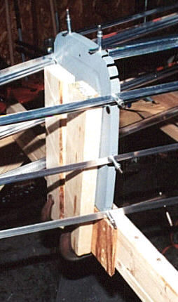 |
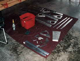 |
Finally its time to disassemble the whole thing and prime all unprimed parts. |
| With all the parts primed, I riveted it together. Now the plane is starting to take shape even if it is still upside down. | 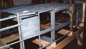 |