The Fuselage (Page 4 of 5)
Journal Cover Page Page 1 Page 2 Page 3 Page 5
(To navigate the photo journal, click on the tabs on the right and the links at the top or bottom of this page.)
Out of the Jig |
|
 |
|
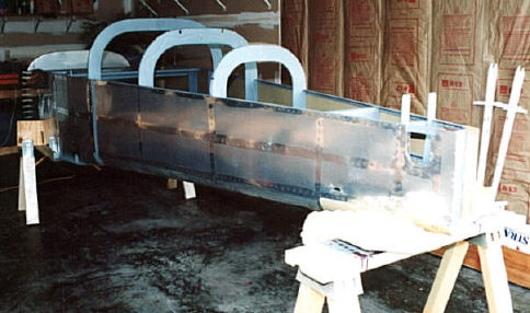
| Finally, the fuselage is out of the jig and sitting right side up. Now the project can really get started. There is all of a sudden a ton of little things to do. | |
| Here is an inside view from the firewall looking back. | 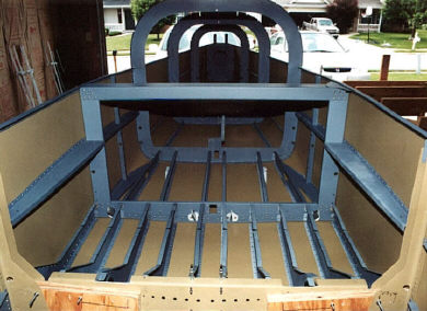 |
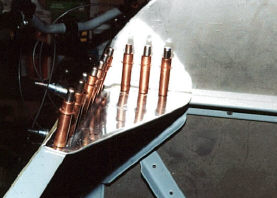 |
This bracket goes on each side where the main longerons meet the firewall. I has just been drilled in place. They come with a simple bend, but had to be augmented with a second bend to create an "S" bend to conform to the two channels. It wasn't too hard to do. |
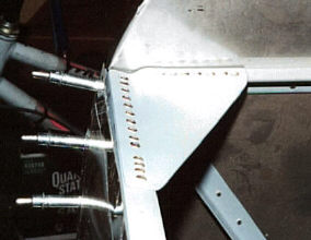 |
Here is the same bracket after priming and riveting. |
| This is the F-604E channel that forms a finished cap on the F-604 bulkhead. It has to be drilled and cut to allow for the bend about 2/3rds down. | 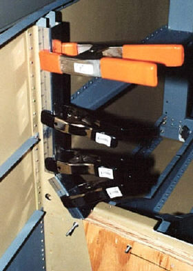 |
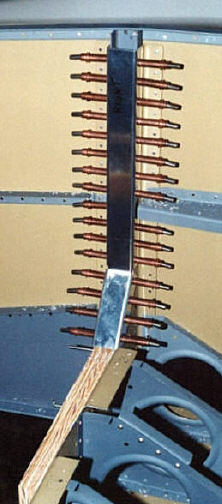 |
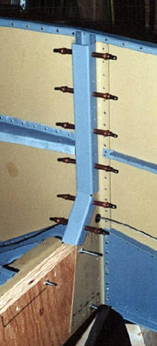 |
| The channel has been drilled has been drilled, primed, and is ready to be riveted, but that will be done later after access to this part of the bulkhead is no longer needed. | |
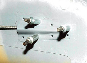
| Both sides of both the F-607 and F-608 bulkheads get tied into the main longerons with brackets. Here is one after drilling and priming and before riveting. | 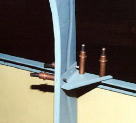 |
 |
Here is an extra. Its a fairing that covers the rudder cable as it exits the side of the fuselage near the rear of the fuselage. I made it up from some scrap aluminum, then drilled and riveted it in place. It turned out pretty well. |
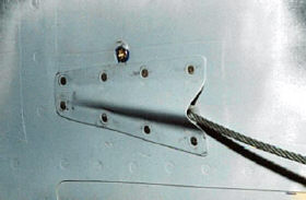 |
This one is from the left side. I like the way it turned out better. You can see the screw that holds the clamp for the rudder cable exit tubing. |
| Here is what the rudder cable exit looks like from the inside. The plastic tube is held in place with a small bracket held in place by one screw as seen in the picture above. | 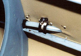 |
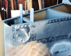 |
This is the access panel for the elevator bell crank. The only reason there are four screws on the top side is because I had mistakenly drilled into the longeron for skin rivets. I was just trying to make use of the holes. Had I to do it over again, I would have used the holes for plate nut rivets and put only three screws. I would show you the other side, but this one came out better. |
| Here is what it looks like from the inside. | 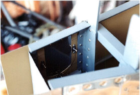 |
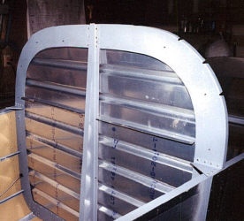 |
The baggage bulkhead panels are cut and fitted into place. This shot is from the rear looking forward. |
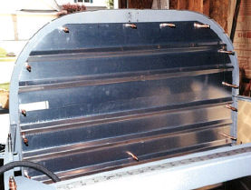 |
And, this shot is from forward looking to the rear. The holes and rub blocks for the shoulder harness cables are not drilled yet. |
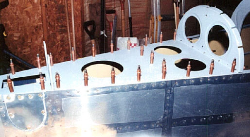
| All the lighting holes are cut in the aft deck and it is ready to be drilled to the fuselage. First, the whole fuselage is leveled in several places to make sure there is no twist. Once you get the front end level, all you have to do is twist the tail in your hands as necessary while tightening down the clamps on the aft deck. Its amazing how much more rigid the whole fuselage becomes once this deck is secure. | 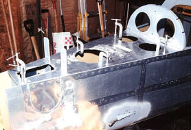 |
 |
|
| Now, the aft deck has been drilled and primed and is ready for riveting. | |
 |
|
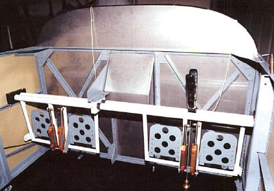
| I used a plumb bob hung from a clamp to make sure the pedals were tilted the right amount. Because one pedal is behind the other, you have to do something like this to make sure the brake pedals come out with the same angle so you don't end up with more leverage on one brake than the other. This seemed to work very well. Once the angle is set, the holes can be drilled for the pivot bolts. | |
| This is a close up of the plumb bob procedure. All you have to do is sight down the rudder pedals from the side and make sure the bottom of the steel tube for the left and right pedals are lined up with the string on the plumb bob. Then, using a angle finder, adjust the brake pedals until they are the same angle, I set the tilt back at about 7 degrees. | 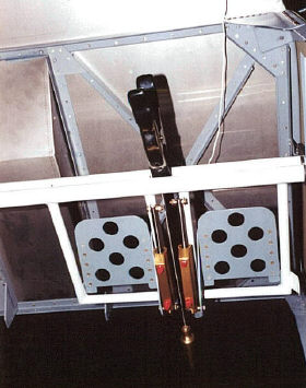 |
 |
|
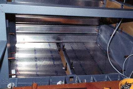
| The baggage floor panels are being fitted and drilled. Maybe its my woodworking and home improvement bent, but I scribed the sides of the floor panels with a cheap compass to fit them. It worked great. They fit snug and perfectly shaped to the side sides. I don't know why this method wasn't called out in either Van's instructions or the Frank Justice notes. | |
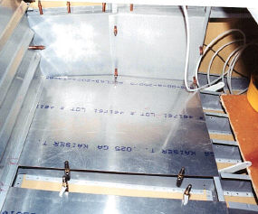 |
This is a side shot of the left baggage floor panel. You can see the baggage bulkhead panel to the left and the left side panels straight ahead. |
| Ah, one of the many uses of duct tape. This is what I came up with to hold the seat floor ribs in place for the floor panel drilling. These ribs are particularly flimsy and have to be braces in some way. This method was marginally successful. I think that I would do it again, but would take greater care to hold the ribs during drilling. They tend to wander a bit as the drill bit comes in contact with them. | 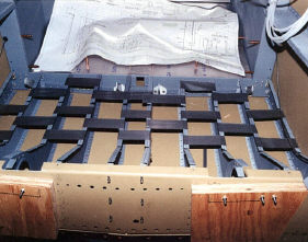 |
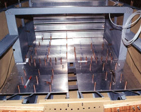 |
More floor panels in place. |
| Your looking at the seat backs from the front. They have been built and are assembled here with clecoes and set in place. | 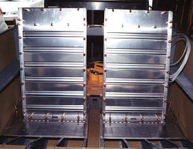 |
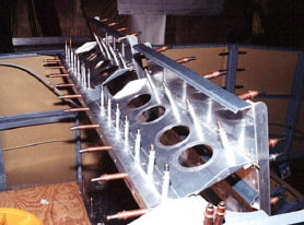 |
This is what holds the top of the seat back to the seat back bulkhead. This support panel is hinged so that it can fit into the two slots provided for adjustment. |
| Thanks to help from Bill and Bob, the aft top skin and the forward bottom skin are finally riveted to the fuselage. | 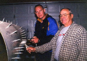 |
| There are just some things you just can't do without help. Riveting skins is one of those for me. | 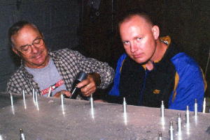 |
 |
|
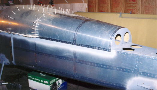
| Here is the aft top skin after riveting. Sure is nice to get rid of some of those ugly clecoes. | |
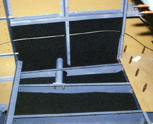 |
The sound proofing insulation is installed in the baggage floor and side panel. There is a section of it cut out to accommodate the rudder cable that passes through the side panel. |
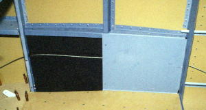 |
I used a 3M spray adhesive to apply the insulation to the inner surface of the skin. The baggage floor and the aft side panel is riveted in place. The forward side panel is removable as shown here to allow rudder cable and flap mechanism inspection. |
 |
|
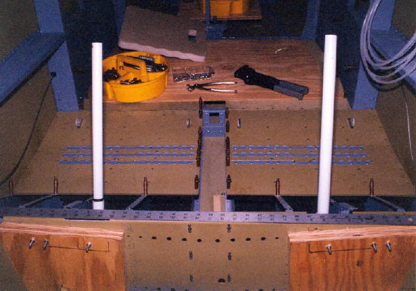
| The seat floor panels have just been riveted in place. Soon this space will get more cluttered as the seat backs go back in and the electric flap housing is re-installed. | |
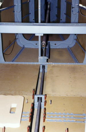 |
This shot shows the elevator control tubes fitted and in place. |