The Fuselage (Page 3 of 5)
Journal Cover Page Page 1 Page 2 Page 4 Page 5
(To navigate the photo journal, click on the tabs on the right and the links at the top or bottom of this page.)
Skinning the Fuselage |
|
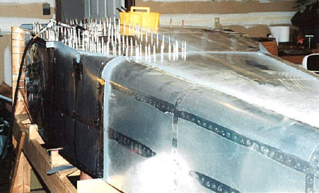
| The fuselage skins are fitted and drilled from aft forward. This is the first one to go on. | 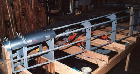 |
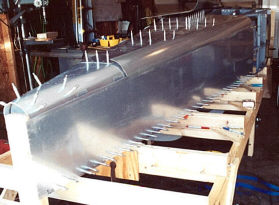 |
In this picture, the aft side skins and the bottom skin are being fitted and drilled. |
| Here is the aft side skin looking back. Its clamped in place ready for drilling. | 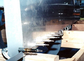 |
| The aft side skin looking forward. Clecoes are in the first few holes drilled through the skin into the main longeron. | 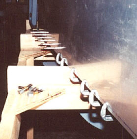 |
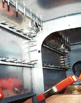 |
Here is what it looks like from the inside of the left side skin with all the holes drilled. |
 |
|
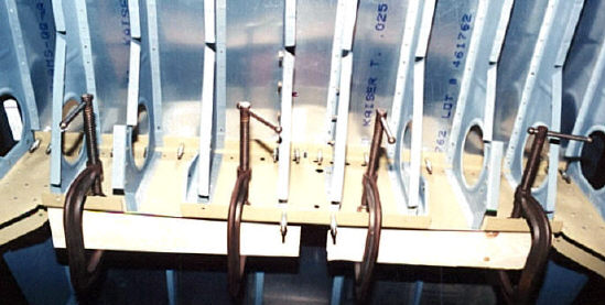
| Fitting the bottom skin is in progress. The clamps hold some wood blocks used just to make extra sure the bulkhead stays straight during the drilling process. | |
 |
|
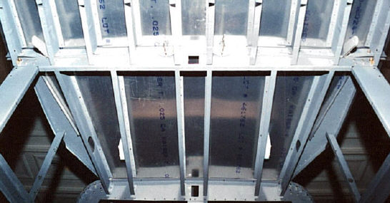
| Here is a view of the bottom skins ready for drilling. I pretty much drilled all the ribs and bulkheads first and then back drilled the skins. | |
 |
|
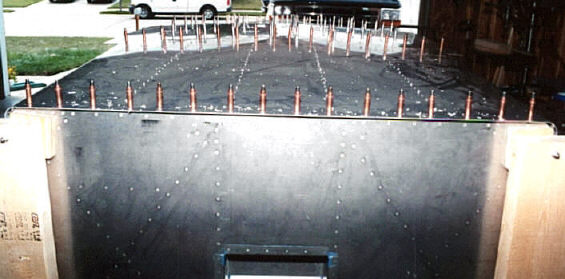
| Here is a shot of the forward bottom skin with the fire wall in the foreground. The floor stiffeners are drilled and clecoed from underneath. | |
 |
|
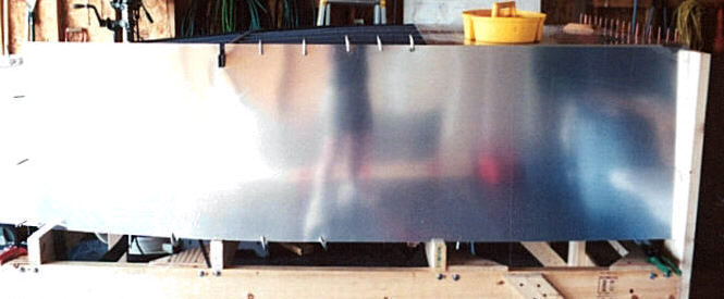
| The left forward side skin is ready for some fitting and trimming. | |
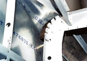 |
Here is one of the trickiest parts of skinning the fuselage. This is the inside of the bottom corner curve. Notice that tabs have been cut in the aft side skin along the curve to match the tabs already formed in the bulkhead. This is done, so that the the tabs may be bent upward slightly to meet the forward side skin and form a better fitting joint. The tabs are traced onto the forward side skin so that it can be trimmed close to where the tabs bend. |
| Once trimmed and drilled, the joint looks like this from the inside. | 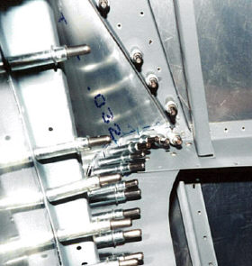 |
| And, like this from the outside. | 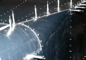 |
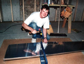 |
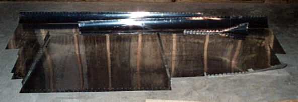
With all the skins drilled, its time to dimple. Its too hot in the garage anyway. The basement is much more comfortable for this kind of operation in mid summer. |
 |
|
| Fast forward and all the skins are deburred and dimpled. | |
| Thanks to help from Gary Mayer, the riveting can finally begin. | 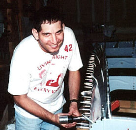 |
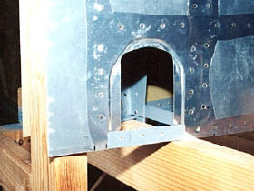 |
I almost forgot to take a picture of another little special item, the rear control access opening. I decided to go with a joggled opening like the way the RV-8 kits come now. As you can see, it wasn't quite as smooth as I had hoped. The problem was that the joggling tool I got from Avery can't turn on a very small radius. |
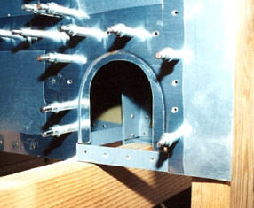 |
Applying the lesson to the right side, I made the cut out in more of a mouse hole shape. This worked much better. One of these days, when I've got nothing better to do, I'll install some nut plates and make the access doors. |
| After a couple of hours, we had the first skin riveted in place. At this rate and having to wait for help, it is taking some time to make progress. | 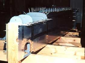 |
 |
Sometimes you just have to stop what your doing and take in a rainbow. |
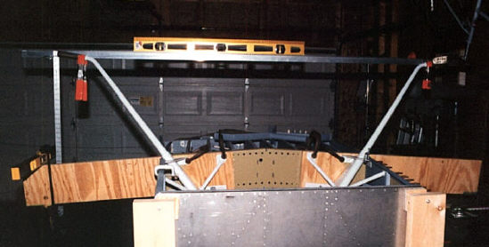
| Because there isn't enough room in my two car garage to install the wings, I had to make up some false spars to simulate the wing for drilling the landing gear mounts. An aluminum angle clamped across from one gear leg to another keeps them level while the mounts are positioned for drilling to the fuselage. With this method, you have to make sure the the vertical distance from the tip of the gear leg down to what would be the bottom surface of the wing is exactly the same from one side to the other and matches the plans. To do this I extended the plane of the false spar with an electronic level and measured down from the gear leg with a metal yard stick. | |
 |
|
| There is one more thing to do while the gear mounts are in place. That is to make a template for cutting the hole in the bottom forward skin where the gear leg goes through it. Here is the tool used for this job. Its a contour gage that can take on a two dimensional shape. I used it to make a paper template one half at a time and then tape the two halves together. The dots on the template line up with the rivet holes in the bottom skin and the wing spar bulk head. | 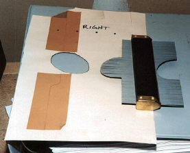 |
| Here is the forward bottom skin marked for cutting with the template. I'll cut it out later with the Dremel ® tool. | 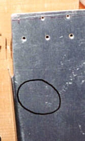 |
 |
|
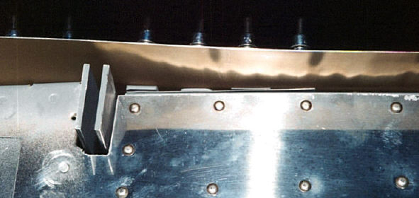
| Here is a "dirty laundry" picture. It shows how I had to shim the bottom skin substantially at the out board rib, but have to make sure it will lie flat where it has to overlap the wing skin. | |
 |
|
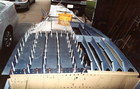
| The left bottom skin is in place and ready for riveting. | |
 |
|
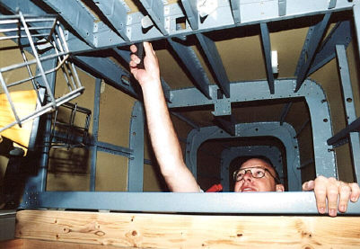
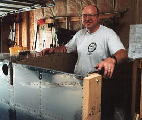
| Riveting partner, Chuck Johnson, is in position to buck the back side of the rivets. | |
 |
|
| After riveting the left bottom skin, the right bottom skin ready. | |
 |
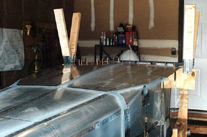
Both bottom skins, riveted in place. Thanks Chuck! |
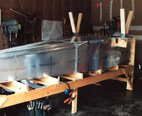
| Temporary legs in place and ready to remove fuselage from the jig. | |
 |
|
 |
Almost there! |