The Wings (Page 4 of 4)
Journal Cover Page Page 1 Page 2 Page 3
(To navigate the photo journal, click on the tabs on the right and the links at the top or bottom of this page.)
Finishing up the Left Wing |
|
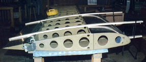
| With the wing back in the jig one last time, it's time to rivet the top skins. Chuck Johnson and I with a little help from Cleco Handler, Karl, make short work of this task. | 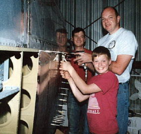 |
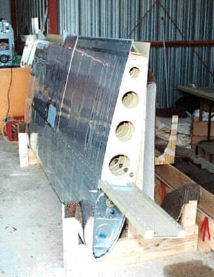 |
With a few left over 2x4's and the wood from the trailing edge brake, I made a wing stand. Here is the finished left wing, and this is where it will stay for a year or two until the the fuselage is ready. |
| This is a shot of the left wing in its cradle after priming. You can see how the wing stand is put together and the scrap carpet pieces on which the wing rests. | 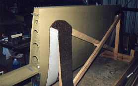 |
Right Wing |
|
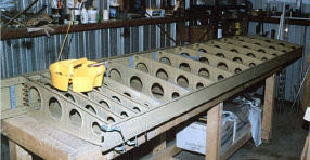 |
Except for a few things, the Right wing is the same as the left. There is no pitot tube to deal with. And, the Spar, aileron, and flap were all built along side their complements on the left. |
| We can use the same wing jig for the right wing, but to keep the spar from protruding over my work bench, it has to go in with the top and bottom facing the other direction. Here, you are looking at the bottom of the right wing with the fuel tank removed. | 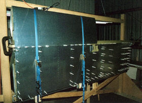 |
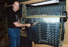 |
I'll spar you all the redundant stuff. The fuel tank, leading edge, and the skins all go together the same as the left wing. But, I wouldn't want you to miss this handsome devil. I don't remember what Chuck is doing here, but I'm sure it is something useful. |
| The landing light is installed in the leading edge and the leading edge and bottom skins are riveted to the wing skeleton. Next, I'll take it off the jig to fit the aileron and flap. | 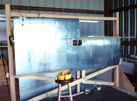 |
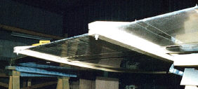 |
Here is something different from the left side. I really didn't like the way that air foil template technique worked out for fitting the left aileron. Ray Hill, an RV builder and professional mechanic, told me about this idea. Its just two 1x2's bolted together at one end. You have to chamfer the corners of the bolted ends. |
 |
To put it to use, all you do is place the joined end over the aileron trailing edge and tie the free ends together with an elastic cord as show in this picture. The boards follow the contour of the wing perfectly and hold it much more firmly in place than that flimsy piece of plywood did. It's also a lot easier to make and store for future use. |
| Here is the finished right wing just after priming. There is a good view of the PVC pipe I chose to use as wiring conduit and it's location. If you were wondering, that other 3/4" hole was a mistake, enough said! | 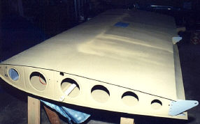 |
|
|
| I've decided to make the wing tips removable by attaching with screws. This will allow easy access to the strobe/navigation light power supplies, landing lights, and auto pilot servo for inspection and maintenance. An aluminum backer strip to hold the plate nuts will be bonded to the fiberglass wing tips in a later step. Here it is being match drilled to the wing skin at the tips. | 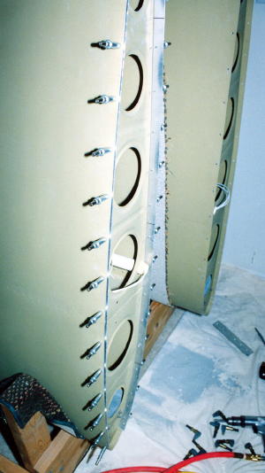 |
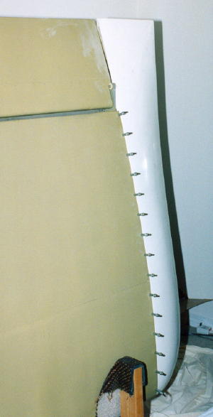 |
Here the wing tip is drilled to the wing skins. Now, I just need to rivet the plate nuts to the aluminum backer strips, bond the strips to the wing tips, and then dimple the holes in the wing skin. |
| With the aileron push rods installed at the bell crank end, that is just about everything I can do to the wing before it leaves my bedroom and can go to the airport where there is room to fit it to the fuselage. | 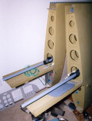 |