The Wings (Page 3 of 4)
Journal Cover Page Page 1 Page 2 Page 4
(To navigate the photo journal, click on the tabs on the right and the links at the top or bottom of this page.)
Odds & Ends |
|
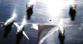 |
Several small tasks still need to be completed before we can close the wing by riveting on the remaining skins. Most of these activities are done in parallel with the wing tank construction. This picture shows the intersection of the tank skin with the aft skin overlap. The korners of the aft skins are sanded down to a taper so they will lay flush with the tank skin. |
| All the skins need to be deburred and dimpled. Chuck and Amanda Johnson dimple the wing skins using the riveting arbor fitted with dimple dies. | 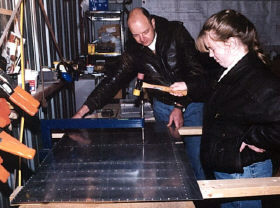 |
| The ribs also need to be deburred and dimpled on the flanges where the skins will attach. Thanks Amanda! She's using the hand squeezer fitted with the dimple dies. | 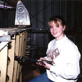 |
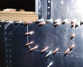 |
On the bottom side of the wing, the aeleron bell crank access panel needs a cover. It is cut out of aluminum sheet and drilled to the skin. |
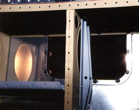 |
Plate nuts are installed on the skin so the cover can be attached with screws. |
| Plate nuts have to be installed in two rows on the main spar flanges to receive the tank attach screws. | 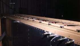 |
| I first drilled pilot holes with the tank in place. Then, clamped the plate nuts on the outside and used their flanges as drilled guides to drill the rivet holes. Next, with the plate nuts removed, the screw holes are drilled out to the final size and dimpled. Finally, the plate nuts are riveted in place. | 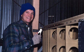 |
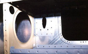 |
Inside the wing next to the aileron access is where the pitot tube will be mounted. Before closing the wing, I have to install the rienforcing brackets that will hold it in place. I'm using the Warren Gretz mount. |
| The aileron bell crank assembly is made up of a bearing sandwiched between two pre-bent plates. I had to drill the all the rivet holes, deburr and prime the parts, and rivet them together. | 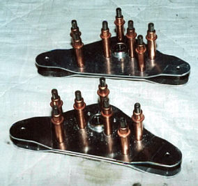 |
| Then it has to be installed in the brackets previously added to a wing rib. A drill bit is used as a pin to hold it in the nuetral position for fitting the aileron later. | 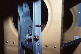 |
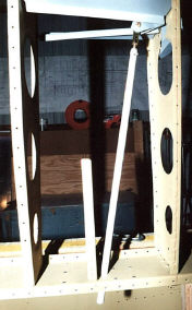 |
With the bell crank in place, the push rod can be cut to length and installed. The rod end bearing that is bolted to the bell crank was riveted to the push rod. Notice that a hole has been cut in the rear spar for the other end of the push rod. I'll connect that end to the aileron later. |
| OK, it's finally time to rivet on some wing skins. Chuck Johnson and John Harris do the honors, riveting the bottom skins, while I'm busy working on the fuel tank. | 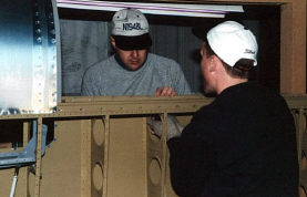 |
| It's steps like this that really make you feel like your making progress. | 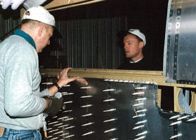 |
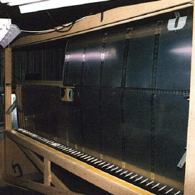 |
All done! Except for the bottom row on the aft spar. The jig got in the way, but they can wait until the wing comes out of the jig. |
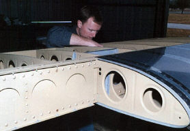 |
No time like the present! John Harris is pressed into service again to finish up that last row of rivets. |
Ailerons |
|
| Because it's easier to fit the ailerons and flaps to the wing before the tops skins are permanently attached, I'll build them now. This time, I have to cut all the lighting holes in the spar. Here, I am deburring those cut outs with a 2" Scotch Brite® wheel on the drill press. |  |
 |
Using a Dremel Tool® to cut the galvanized steel water pipe to length, I make the aileron counter weights. I tried cutting it with a hack saw, but that takes way too long. |
| A couple of short ribs connect the spar to the counter weight and two more ribs extend aft of the spar to the trailing edge. Don't those lighting holes look good? |  |
 |
Here are the skeletons of both ailerons, prepped and primed and riveted together. To save time, I made both the ailerons at the same time. |
| Once again, I have to drill all those stiffeners to the skins. This time its the aileron skins. |  |
 |
What a handsome aileron skin, ready to be drilled to the skeleton. |
| This is the same type of trailing edge brake I used for the elevators and rudder. I decided the other one wasn't good enough, so I made a new one with 2x8 instead of a 2x6. |  |
| What was left of the 2x8 is used here as a weight holding the aileron flat to the table while drilling the skin to the skeleton. Unintended twists in a control surface is a bad thing. | 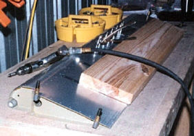 |
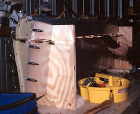 |
With another homemade jig holding the aileron straight, it's time to rivet it together. |
| The aileron can now be fitted to the wing. This picture shows a jig specified by the manufacturer. Its made out of the lid from the wing kit crate that comes with the air foil shape drawn on it. This jig holds the aileron in what is called the "trail" or "neutral" position so the aileron brackets can be fitted to the rear wing spar. | 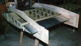 |
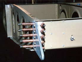 |
Here is the out board aileron bracket drilled and clamped to the rear spar and the out board most wing rib. The nut hanging from the string next to it is the weight on the bottom of the make shift plumb line used to position the wing in the wing jig. |
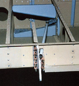 |
This is the in board aileron bracket. You can see the aileron push rod poking down through the rear wing spar. The hole in the spar will have to be enlarged to allow for its full range of travel. |
| After riveting the aileron brackets to the rear wing spar, there is one last thing to do before hanging the wing back in the jig is to fit the aileron gap fairing to the rear wing spar. I clamp the top wing skin in place temporarily and drill the aileron gap fairing to it and the rear wing spar. |  |
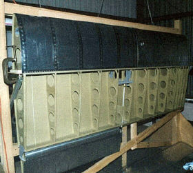 |
Here, the wing is carefully clamped back into the wing jig with the aileron attached. At this point the fuel tank was ready to screw into place on the leading edge of the wing. |
| It's time to enlarge that hole in the rear wing spar. This is done a little at a time so the hole will be just the right size to allow the specified range of travel but no more. A push rod will be attached to the other end of the aileron bell crank after the wings are fitted to the fuselage at a later date. | 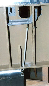 |
Flaps |
|
 |
The flap construction starts by cutting the lighting holes in the spar and then drilling the ribs to the bottom skin. |
| Here, the spar, ribs, and bottom skin are clecoed together after drilling. |  |
 |
With the parts prepped and primed, the ribs are riveted to the bottom skin, but the spar is left off so we can have access to buck the rivets for the top skin later. In this picture, I'm drilling the flap hinge to the flap. This is half of the hinge that holes the flap to the wing. |
| A little deburring with a speed deburring tool... |  |
| A little dimpling with the hand squeezer and dimple dies... |  |
 |
And then, the riveting begins. The overlap of the top and bottom skins are riveted together first. |
| Next, the ribs are riveted to the top skin. |  |
 |
Riveting the hinge and the spar into place finishes it up. |
| Here it is, a finished flap. |  |
 |
Got to take the wing out of the jig again--this time to install the flap brace and the other half of the flap hinge. To prepare the flap brace for this step, I had to cut out all the lighting holes and modify the inboard end to fit around the rear spar reinforcing bars. |