The Wings (Page 1 of 4)
Journal Cover Page Page 2 Page 3 Page 4
(To navigate the photo journal, click on the tabs on the right and the links at the top or bottom of this page.)
Wing Kit |
|
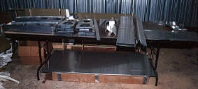 |
After the wing kit arrives, the first task is to take inventory. Soon this pile of shiny aluminum parts will become a set of wings. |
Spars |
|
| The various parts of the wing spars come from the factory bolted together. The rear spars on the the right and the main spars on the left. They are disassembled and all parts are prepped for riveting. | 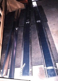 |
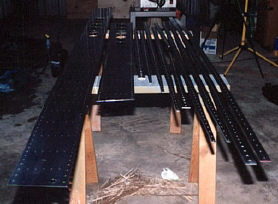 |
Here are all the parts of the disassembled main spars. The pieces are laminated together to form light, but strong, beams that will carry the weight of the plane in the air. Because this structural component is so critical, the spars are match drilled in a factory jig. If any of the parts are nicked either during or after assembly, all the laminates must be replaced with an entirely new set of match drilled set. |
| Once prepped and primed, the riveting can begin. | |
 |
|
| These small aluminum bars serve as stiffeners for the main wing spars. | 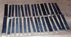 |
| They come pre drilled, but must be primed. I use a one-part, self-etching primer from Sherwin Williams. | 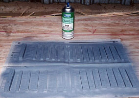 |
| Riveting the larger rivets of the wing spar requires either a pretty hefty pneumatic riveting gun or a riveting arbor. Since I already have the arbor and these are the only rivets in the kit of this size, it didn't make sense to buy the gun. The biggest drawback to the arbor is that a three pound hammer and quite a bit of force are needed to set the rivets properly. If you wack at it too lightly, it requires too many hits to form the rivet and the rivet will become brittle and crack. But, because striking accuracy diminishes with the amount of force used, the risk of missing the plunger and hitting your self increases. | 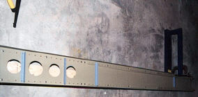 |
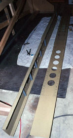 |
After about four hours of riveting on each spar and only three significant knee strikes (ouch!), the task is complete. The round holes are lighting holes where structurally insignificant material has been removed for weight savings. |
Left Wing |
|
| Here is a finished main spar waiting for the marking and laying out of the ribs. | 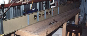 |
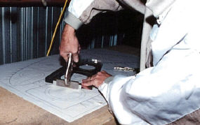 |
It took about two weeks (~40 hours) to prep all the ribs for both wings before they could be fitted to the spar. This process consists of deburring all edges including the lighting holes, bending the flanges 90o to their webs, and fluting the flanges. This picture shows how a hand seamer is used to bend the flanges. |
| One of the drawings provided in the kit is a fluting diagram which indicates a safe location for each flute. Then fluting pliers put a crimp in the flange at each mark. This has the effect of straightening out the bow induced in the web during the manufacturing process. | 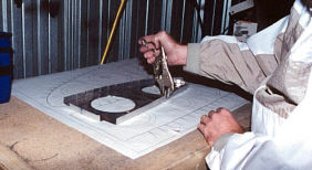 |
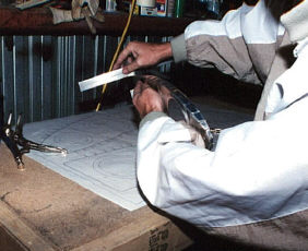 |
What makes this process so tedious is that the fluting and flange bending tend to counteract each other. The flutes take out some of the bend angle and the hand seamer flattens the flutes. So, it's an process that requires patience and persistence. Here, I check the flange and web for square. |
| After laying out the positions of each rib on the left spar, we embark on another iterative process--that of positioning the ribs, testing the fit by overlaying skin sections, and re positioning ribs until the flange center lines are visible through the holes in the skins. | 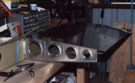 |
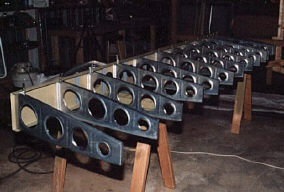 |
All aft ribs of the left wing are clamped to the main spar. The outboard end is to the left. |
| Here, both top, aft skins lay atop the ribs during the final check of their positioning. | 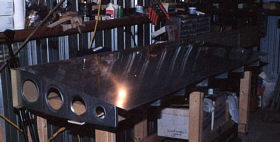 |
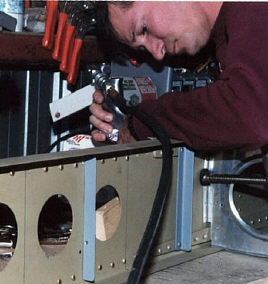 |
Once satisfied with the placement of each rib, their position is marked in the spar web with a thin blue line visible in this picture. Then, one-by-one the forward flange of each rib is drilled for the bolt holes using the holes in the spar, with a brass insert, as a guide. |
| This shot shows one of the ribs bolted in place. Notice that the forward rib flange holes have not yet been drilled into the spar web. | 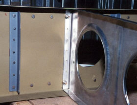 |
| On the inboard ribs (these are in the wing walk area), the bolts actually go through brackets that will be riveted to the ribs instead of into the rib flanges. The ribs are clecoed to the support brackets to make sure everything stays in place during drilling. | 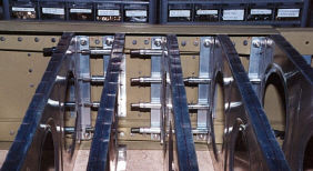 |
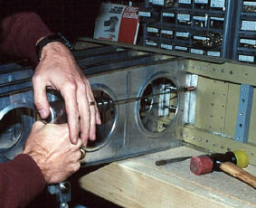 |
Next, the forward rib flanges are drilled to the spar web. Because the rib webs get in the way, it is necessary to use a 12" drill bit. The long bit flexes enough to go in straight forming a round rivet hole. A shorter bit would go in at an angle creating an oval hole that would not be optimal for riveting. |
| Once the aft ribs are all drilled, its time to begin drilling the forward ribs. To make sure they will perfectly line up with the aft ribs, the ribs are clamped together so that the rivet holes in the aft rib can be used as a guide to drill the forward rib flange. | 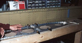 |
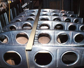 |
The forward and aft outboard ribs are clamped in place after drilling. |
| Now, let's see if the holes in the pre-bent forward skin line up with the forward rib flange center lines. Yeah! Its almost perfect. The bottom of the wing is facing with the inboard to the left. | 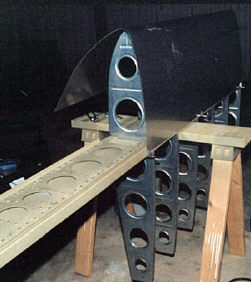 |
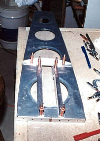 |
One of the ribs has to be modified to hold the aileron bell crank assembly. The bracket parts are made from stock aluminum angle. |
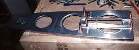 |
I cut the parts on the band saw and smoothed the edges with the Scotchbrite® wheel on the bench grinder. The parts are all tapered to reduce weight. After everything is primed, I'll come back and rivet this assembly together. |
| Here the rear spar, which was built right after the main spar, is clamped in place and all the rib locations marked. | 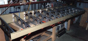 |
| Rear spar is all drilled and clecoed in place. | 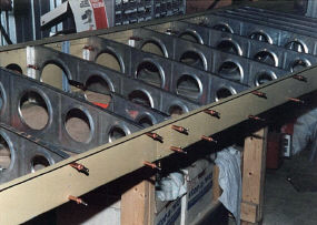 |
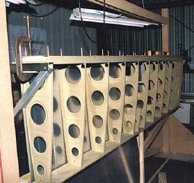 |
At this point, the ribs have been primed and the rear spar has been riveted to the ribs. I'll rivet it later. But, the ribs are just bolted, not yet riveted, to the main spar. The assembly now hangs in the wing jig to keep it straight while I drill the skins to the rib flanges. |
| A couple of temporary plumb lines make sure everything stays straight during the wing building process. Here is one of them. Notice the red line that marks the rib flange center lines. Next, the skins are fitted to the wing skeleton in such a way that these lines are visible through the pre drilled rivet holes in the skin. This picture also gives a good view of those flutes in the rib flanges I discussed earlier. | 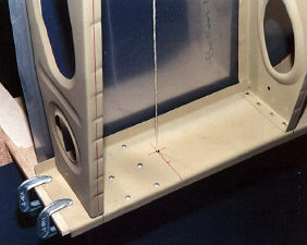 |
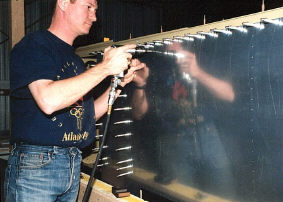 |
With the skins clamped in place and the ribs coaxed into their positions, the skins are drilled to the rib flanges. |
| The bottom inboard and outboard skins are drilled to the wing skeleton and remain clecoed in place. The cutout is for the aileron bell crank access panel./B> | 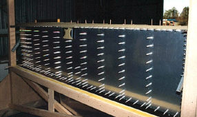 |
| Here are the top skins after drilling. I have also clamped the forward outboard ribs into place on the spar. | 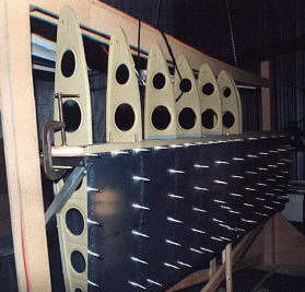 |
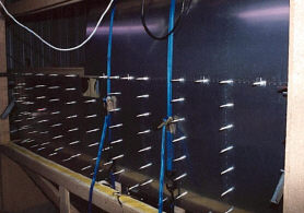 |
Ratchet tie-down straps hold the outboard leading edge skin in place for drilling. |
| With the skins removed after drilling, the rivet holes are visible in the rib flanges. Look at that! They line up with the rib flange center lines and fall right between the flutes. Also visible is the red line on the spar flange which marks where the aft and leading edge skins will butt up against each other. The accuracy of this mark is critical for fore/aft alignment of the aft skins for drilling. | 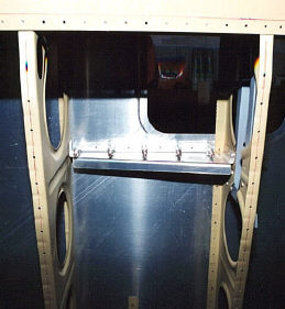 |
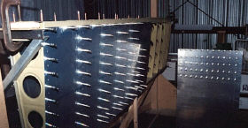 |
A small section of skin called the wing walk doubler is added underneath the inboard aft skin to reinforce the wing walk area. After drilling the outer skin to the wing skeleton, I removed it and drilled through its rivet holes into the doubler. In this picture the outer skin is propped up with the doubler clecoed in place. The doubler is on the back side and is not visible here. |