The Wings (Page 2 of 4)
Journal Cover Page Page 1 Page 3 Page 4
(To navigate the photo journal, click on the tabs on the right and the links at the top or bottom of this page.)
Left Fuel Tank |
|
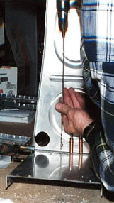 |
After all the ribs have been prepped, the tank constructions begins by laying out the rib locations on the back baffle and then drilling the ribs to the baffle. Here is that 12" long drill bit again. |
| Drilling the ribs to the baffle is complete. The tank ribs do not have lighting holes. Instead, the solid ribs act as baffles to keep the fuel from sloshing around too much in flight and getting away from the fuel pickup line. That would be a bad thing. However, we do have to drill some holes in the center ribs to allow the fuel to flow from one baffle to the next during refueling on the ground and consumption in flight. | 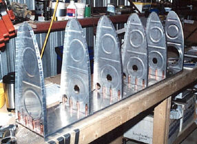 |
| You may have noticed in the picture above that the inboard rib has a big hole in it. This is where the fuel pickup and fuel sender (gauge) access panel will attach. First the hole is cut out and then the reinforcing ring and platenuts are installed. | 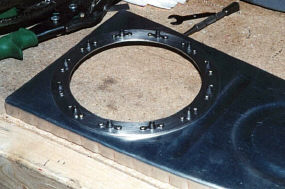 |
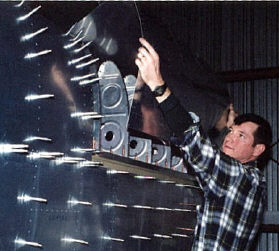 |
Now the assembly can be placed on the wing structure for the fitting of the tank skin. Using those same tie down straps used on the outboard leading edge skin, the skin is held tight for drilling to the ribs and baffle. This process takes a lot more patience than it did for the leading edge skin because the solid tank ribs are not as accessible as the outboard ribs that had lighting holes. |
| Next, we move to the tank skin. Before it can be drilled or riveted to the skeleton, it needs some stiffeners. This will reinforce the skin so it can hold the extra weight of the fuel in the tank. Using aviation tin snips, the stiffeners are cut out of light aluminum angle stock. | 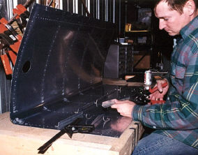 |
| Once all the stiffeners are cut to shape and the edges smoothed, I lay out the rivet hole pattern. The stainless steel rivet spacer you see here is a great labor saving device for laying out evenly spaced rivets. | 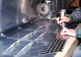 |
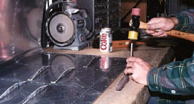 |
Then, I use a center punch to make a small detent on each hole mark so the drill bit won't slip. |
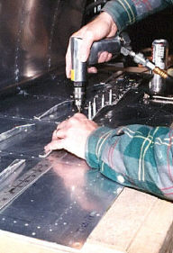 |
Now I can drill the stiffeners to the skin using the same technique as for the control surfaces. |
| The newly drilled holes must be deburred in both the stiffeners and the skin. | 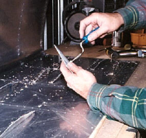 |
| They must also be dimpled to receive the flush set rivets. Here, I use a hand squeezer with dimple dies mounted to do the work. | 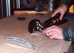 |
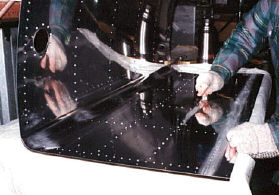 |
With the rivet holes deburred and dimpled, I moved on to prepping the surface of the skin around the rivet holes with a stainless steel welder's brush. This will help the tank sealant adhere better. |
| Time to mix up some "goo"(sealant) and go at it. Here, the filler flange and stiffeners have been riveted in place. This is the result of the first of four sessions riveting the tank. A couple of great ideas from other people's web sites really helped. First I cut up paper towels into small squares using one each time a bit of the black sealant got on anything. Another was to cut the ends of some popcycle sticks square and use them as disposable mixing and applicating sticks. | 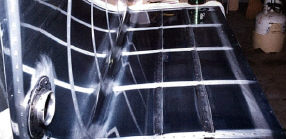 |
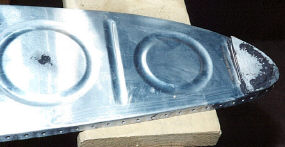 |
The leading edge of the out board rivet has to be reinforced with a small plate that I cut to shape for this purpose. Notice also the tooling hole in the center of the large circle has been sealed with a rivet and some sealant. |
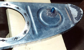 |
The leading edge of the inboard rib gets the same treatment. This is also a good time to mount the fuel vent fitting and seal it with more of the grey goo. |
| Construction of a simple jig is necessary to hold the assembly together during the riveting process. Helper John Davis sports a role of electrical tape which he has placed over the rivet holes. It is removed progressively before each rivet is set. The tape helps to keep the mess down, and therefore preserve some sanity, by keeping the sealant from oozing out as you put the ribs in place. | 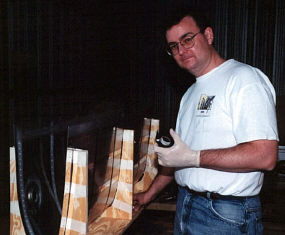 |
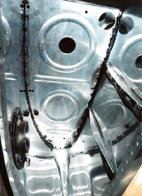 |
Session two involves riveting the four inner ribs to the tank skin. |
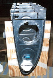 |
In session three, the inboard and out board ribs are riveted in place and sealed. |
| This is the inside of the fuel sender access plate. I had to make a little bracket to hold the fuel pick up fitting. This bracket keeps the fitting from turning when the fuel pick up line is tightened from the other side. The platenuts will receive the screws that hold the fuel sending unit in place. | 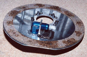 |
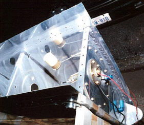 |
The last thing that needs to be done before the back baffle can go on is to calibrate the fuel sending unit. The wire arm holding the float is bent until the fuel gauge reads empty and full at the appropriate limits of its travel. |
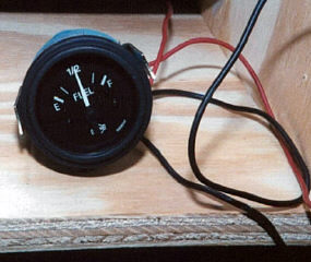 |
I temporarily connected a fuel gauge to the fuel sender powering it with a 12 volt car battery. |
| The fourth and final session riveting the tank is attaching the back baffle. A bunch of home made wooden clamps hold the skin and baffle flanges together while the sealant sets. | 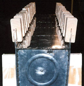 |
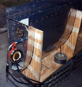 |
Once all the sealant has had a chance to dry, it is tested for leaks. This is done with air pressure. To set this up, I put tape over the filler cap, because its not designed to be air tight, put a cap on the fuel vent fitting, and attached the contraption you see in the picture to the fuel pickup line. The tester is made up of an old tire valve stem in a rubber T coupling that couples it to the pressure gauge and fuel pickup fitting on the tank. With my compressor set as low as it would go, I filled the tank to 1.5 psi. Then, I brushed soapy water all over every rivet, joint, and fitting looking for bubbles. On one tank, I drilled out a rivet or two and replaced them with flush set blind rivets. And, I had to drill out a couple of the blind rivets hold the baffling to the ribs because they had cracked. With those corrections, both tanks will hold 1.5 psi for over 4 hours. |
Left Leading Edge |
|
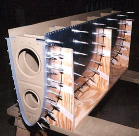 |
In between fuel tank building sessions while the sealant was drying, work progressed on other parts of the wing. This is the out board leading edge in the jig ready for riveting. |
| John Harris and Chuck Johnson riveted the leading edge together for me. Thanks, guys! | 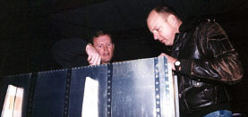 |
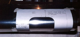 |
Its easier to install the landing lights before the leading edge is riveted to the wing structure. Here, the template for the Duck Works landing light cut out is taped in place. |
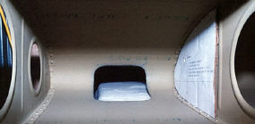 |
With the cut out finished, another template lays out the landing light's bracket attachment holes in the leading edges of the two out board ribs. |
| The pre-shaped plexi-glass lens is clamped into place after drilling it to the wing skin. To protect it from scratches during the construction process, I've covered it with masking tape. The loop of duct tape serves as a handle that helps to pull the lens tight to the skin during drilling. | 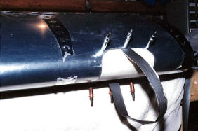 |
| The holes are counter sunk so that the stainless steel flat head screws will lay flush with the skin and not cause any additional drag. | 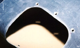 |
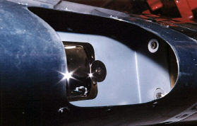 |
The landing light bracket is riveted together, the plate nuts are installed in the ribs, and the bracket is screwed into place. |
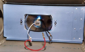 |
Here is the back side of the bracket with the light installed. Wiring will come later. |
| Now it's time to permanently affix the leading edge to the wing. First, the plastic coating is removed along the rivet line with a soldering iron. | 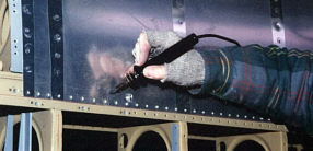 |
| After melting it loose, the plastic is peeled back. |  |
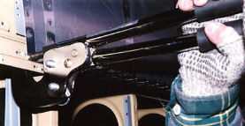 |
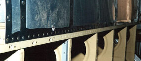
Finally, I can rivet the leading edge skin to the main wing spar flange with a hand squeezer. |
 |
I can not show it in a picture, but with this rivet line secure on both side, the fore and aft wing ribs are riveted together through the main spar web. |