The Finish Kit (Page 3 of 3)
Journal Cover Page Page 1 Page 2
(To navigate the photo journal, click on the tabs on the right and the links at the top or bottom of this page.)
 |
|
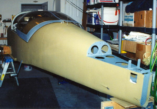
| The fuselage is cleaned up and covered with a protective layer of zinc chromate primer. The wings are in the master bedroom and the tail feathers and control surfaces are in the upstairs bedrooms. Now all I need is an engine. | |
Landing Gear |
|
| Wish I had this photo while I was trying to figure out how everything went together. You can see the brack caliper with the fitting on the top turned forward and the fairing mounting plate in place. | 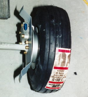 |
 |
|
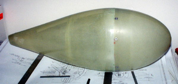
| Here is the wheel fairing halves screwed together. Its been filed and plate nuts installed. Next, it needs some cut outs to fit over the gear leg and allow room for the brake line. | |
| One of the main gear leg fairings is getting its piano hinge drilled in preparation for riveting. | 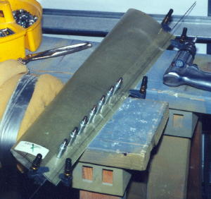 |
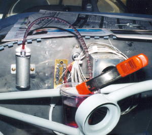 |
Filling the brake lines with fluid and bleeding them of air was a royal mess. I finally came up with a system that seemed to work pretty well. I had a plastic fitting laying around about the right size to connect the clear plastic tube to the brake fluid reservoir. It goes to an overflow cup during the bleeding process. |
| Fluid is pumped in at the low point in the system via a plastic tube pushed over the drain valve at the bottom of the brake caliper. This is the right side from the rear. | 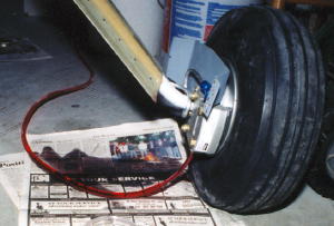 |
| Here you can see the fluid can and the pump is used to draw fluid out of the can and up into the caliper. This set up allowed me to pump and monitor the air coming out at the top of the system (brake fluid reservoir) and into my overflow cup. | 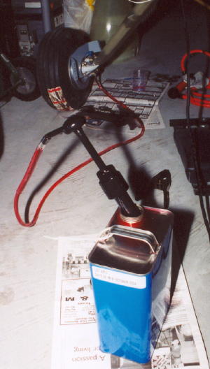 |
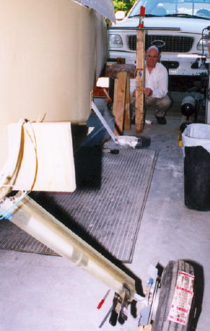 |
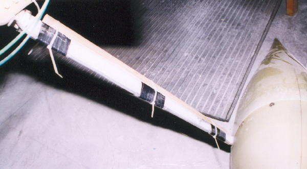
You can just barely see the string used to align the main gear fairing. Because the horizontal stabilizer was not in place at the time, we clamped a steel pipe to the aft deck as a straight edge. My Dad is holding the string against a reference mark on a plumbed upright straight edge. This procedure ensures the gear leg fairing is aligned with the relative wind so that the fairing has no unintended aerodynamic effects. |
 |
|
| The picture quality is not good, but you can make out the nylon tie wraps used to hold the wood stiffener in place on the left main gear leg. In three places, I used a small piece of clear plastic tubing over the aluminum brake tube and held it in place on the gear leg with black electrical tape. | |
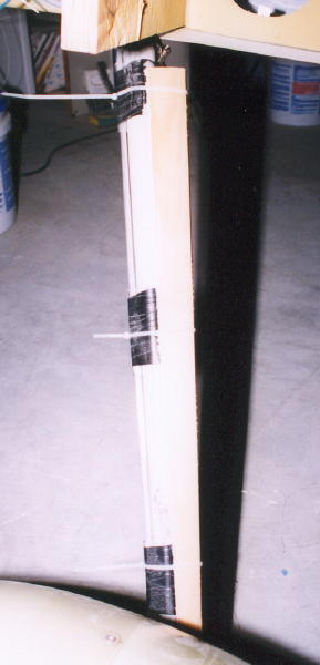 |
A different view of same gear leg. This clamping technique allowed just enough movement of the wood stiffener under the gear leg fairing so that both could be positioned at the same time. |
| Once its final position had been determined and marked, I removed the plastic tie wraps and locked it into position permanently with a wrapping of fiber glass cloth and epoxy. | 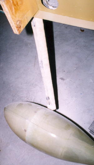 |
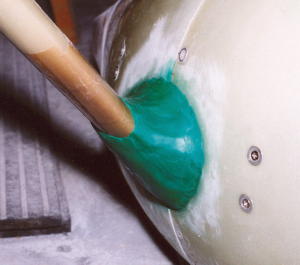 |
Modeling clay makes a pretty good mold for the intersection fairing. |
| This is same as above, but from the rear looking forward at the left main gear. | 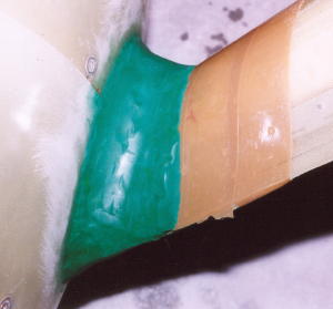 |
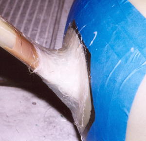 |
After the first lay up. There are many more layers to go, but this gives you an idea of the shape and the process. The black electrical tape is great for bending around curves and resisting sanding. |
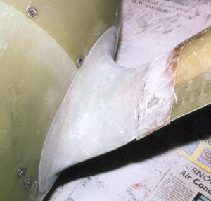
| Another view from the back side. | 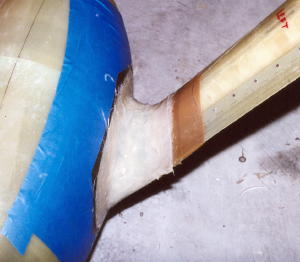 |
 |
A little bit different angle. The blue painters tape is just there to make sure the epoxy doesn't get in the wrong place. |
| After a lot of sanding. | 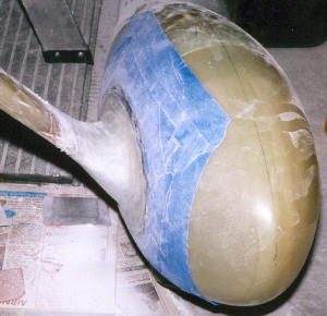 |
 |
|
| With the masking removed, you can see the fine edge that is about the thickness of the electrical tape. Now it just has to be feathered out smooth. | |
 |
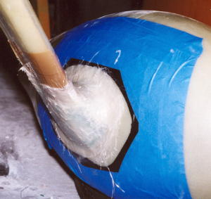
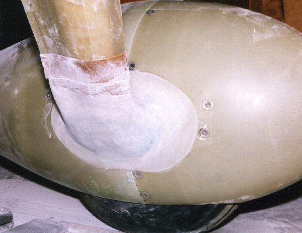
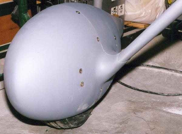
Here is what it looks like from above and behind. Now, with a cut off wheel, I split the intersection fairing vertically so the wheel fairing can be removed. |
 |
|
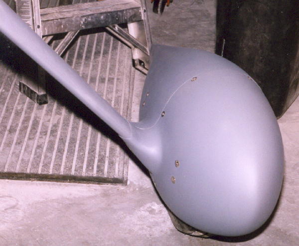
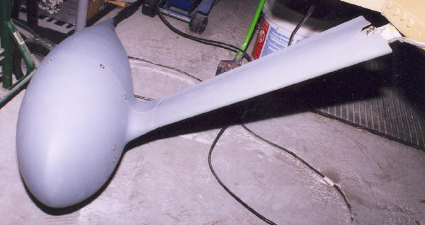
| After cleaning up the fairing halves and doing a little filling here and there, I primed them. Sure looks a lot better. | |
 |
|
| And, here is the right side. | |
 |
|
| I think the second side came out a little better. Pretty soon I will have all the skills needed to build another RV. | |
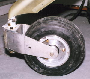 |
Here is a shot of the nose wheel. I went through three inner tubes before I managed to get the wheel halves bolted together without pinching one. |
| Couldn't resist a picture of the "Experimental" decal in place. | 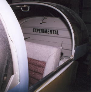 |