The Finish Kit (Page 1 of 3)
Journal Cover Page Page 2 Page 3
(To navigate the photo journal, click on the tabs on the right and the links at the top or bottom of this page.)
Canopy & Windscreen |
|
 |
|
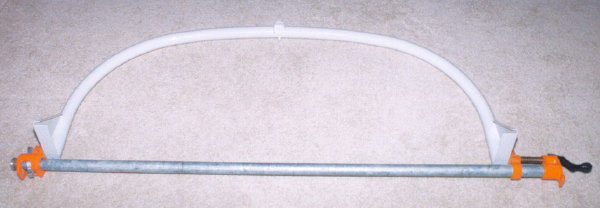
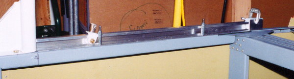
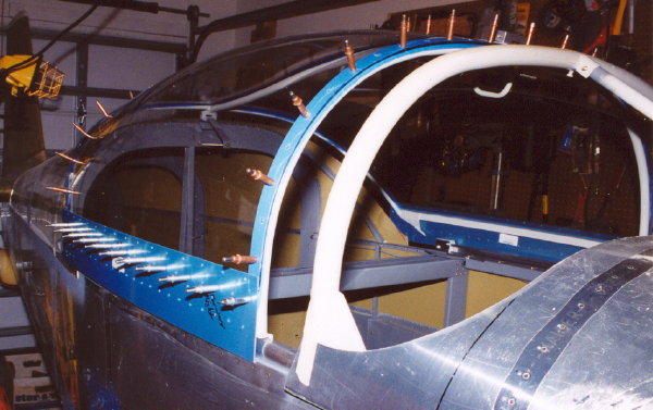
| The canopy roll bar, shown here, had to be flexed almost 3 inches to get the required 3/4 inch reduction in width to fit the fuselage frame. I used the bar clamps in this picture to do the job. | |
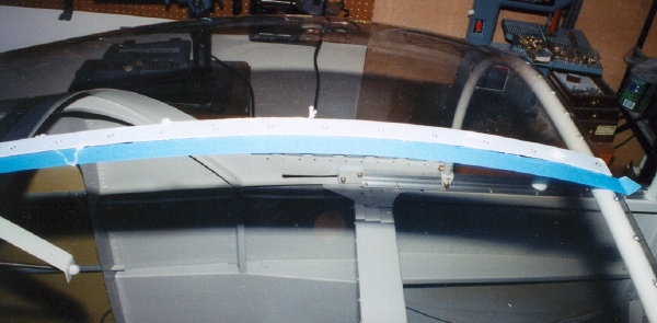
| Here the roll bar is clamped to the fuselage during the fitting process. | 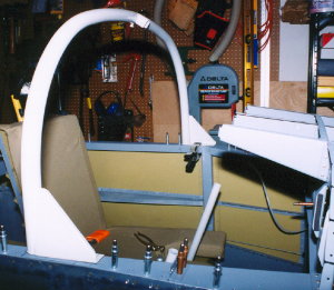 |
 |
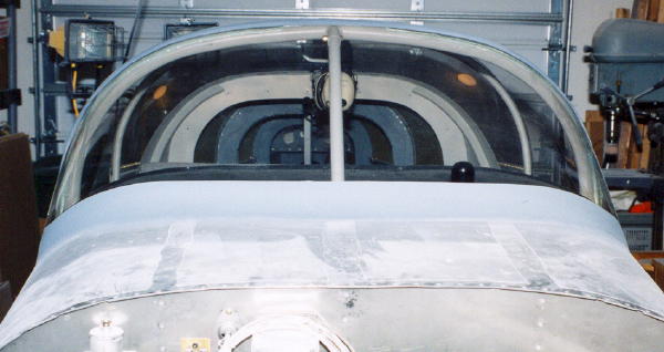
With the forward top skin temporarily in place, the support bar can be checked for fit. |
| One of these supports gets riveted to each side of the top skin. | 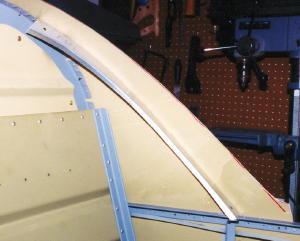 |
 |
|
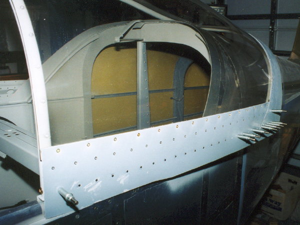
| The canopy rail being fitted to the canopy deck. | |
 |
Here is the aft canopy rail riveted together and screwed to the fuselage. |
| The canopy latch assembly is pretty straight forward. | 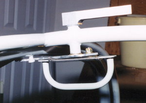 |
 |
|
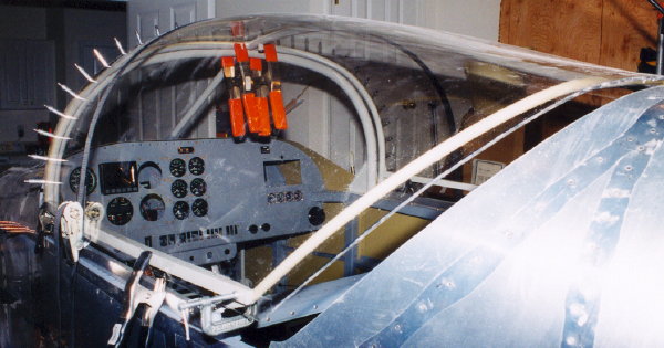
| Using various clamps and ratchet straps to hold everything in place for drilling the canopy to the frame. | |
 |
|
| Another perspective. | |
| I spent a lot of time polishing the canopy before permanently riveting it to the frame on the assumption that its easier done on the living room floor. I have mixed feelings about the hole process. I used the Micro Mesh kit and I'm not sure it wouldn't have been better to do it after flying it some. The project would be several hours further along and scratches keep appearing. Some builders leave the plastic in place longer, but I just couldn't see how things were lining up. | 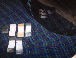 |
 |
|
| Drilling the side skirts. | |
 |
|
| Helper, Steve Barry, bucking while I rivet the side skirts. | |
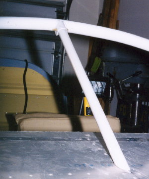
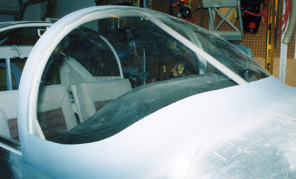
| Here is how the wind screen interface with the roll bar and top skin turned out. There is very little help in the plans on this. You kind of have to go with what seems right. I'm not sure I like my solution, but its done and that's that. | 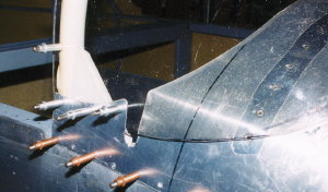 |
 |
|
| Seemed like a good time to paint the interior before riveting the canopy and bonding the wind screen. | |
| Also, need to cover the glare shield. I used some vinyl that had no shine to it that I found at the local fabric store. Its bonded in place with contact cement applied with a roller. I put the cement on about 1" of the good side of the vinyl and stuck that down to the glare shield. Then, pushed a split piece of vinyl tubing over the edge of the glare shield trapping the vinyl material. Now, with the vinyl hanging down in the cockpit, I very carefully folded it back over the tube and pressed it to the glare shield progressively from the edge forward . | 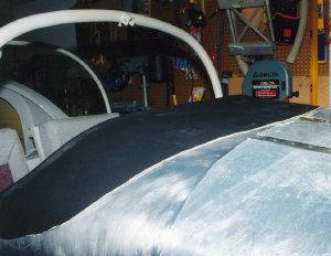 |
 |
|
| With Lexel sealant procured at the local ACE Hardware store, I riveted and screwed the canopy to its frame. The masking tape helped with cleaning the excess sealant. | |
 |
|
| Getting ready to put rivets in the bottom row on the left canopy side skirt. | |
 |
|
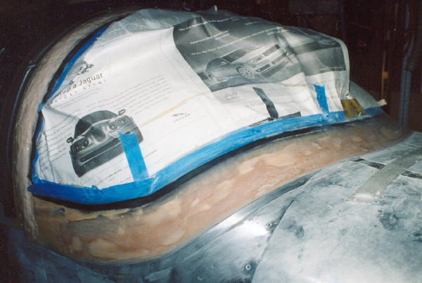
| Bonding the wind screen to the forward top skin. Isn't this fun! | |
 |
|
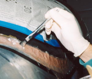
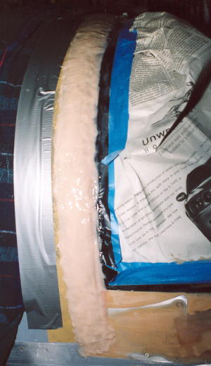
| With a temporary foam backer rod in place on the inside of the wind screen, I placed a thickly epoxy mixture in the void and let that set up a little before layering progressively wider glass strips until approximating the desired shape. More fun! | |
 |
Two layers of electrical tape provide a form boundary (masking) for the epoxy. The electrical tape is preferred in this application because of its ability to curve easily without becoming wrinkled and it stands up to the sanding process better than painters tape. |
 |
|
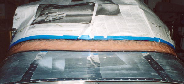
| Now, I just have to let it dry and then start the many iterations of sanding and filling until I get tired of it. | |
 |
|
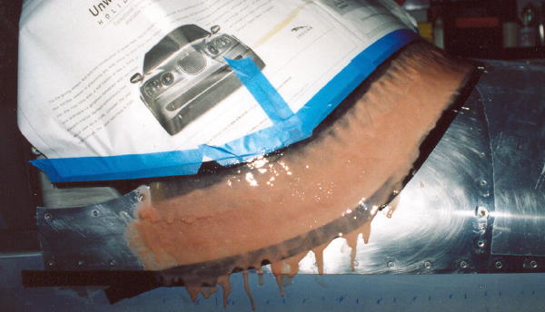
| Oops! Guess I should have masked a little farther down. | |
 |
|
| This shot shows the layers of fiber glass cloth used at the top of the wind screen where it will overlap with the canopy when the canopy is in the closed position. You can see one of the screws securing the wind screen to the role bar. You can't see the role bar through the plexy because I had to use a lot of Super Fill to fill the gap and make it feel more solid. | |
 |
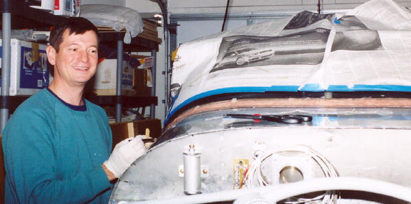
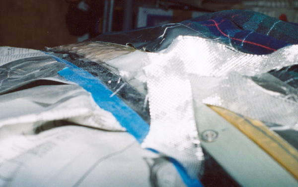
This the the right side with the canopy closed and the wet lay up before sanding. The canopy leading edge is covered by brown packing tape which serves as a release agent. |
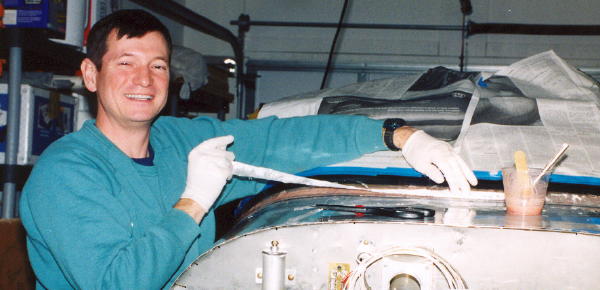
| This photo is taken from high to the right. The wind screen is covered with newspaper and the canopy with a flannel sheet. I've got to do the left side before the epoxy sets up too much. | 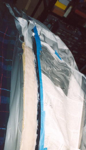 |
 |
|
| Pretty hideous looking, but that is what it takes (at least with my beginner skills). | |
 |
|
| Wow! What a difference. | |
 |
|
| After about a million and a half iterations of sanding and filling. | |
Cabin Floor |
|
| This is the fuel selector valve supporting structure. | 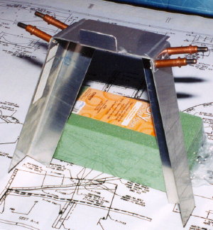 |
| Here it is in position in the cockpit. I decided to position it under the seat floor skin as you can see, purely because I thought it was a cleaner look. |  |
 |
|
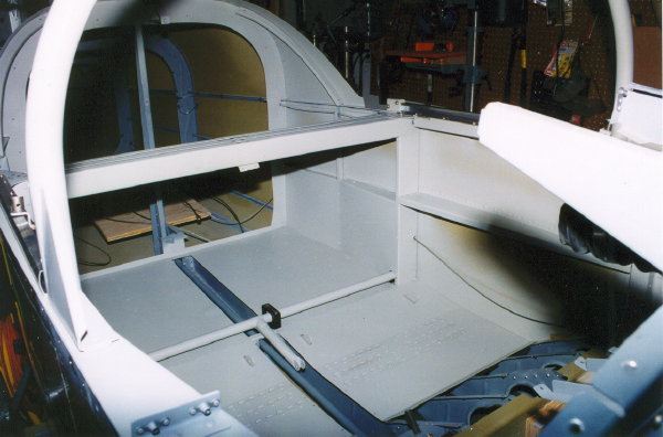
| The next few shots show the construction of the floor in the forward cabin area. Van's leaves this to the discretion of the builder, but I can't imagine that it would be good to leave it with no flooring. This first picture shows the 3/4" angle stock used to create a surface to which the floor is fastened. I riveted them to the floor stiffeners before drilling the floor to the supports. Then there wasn't enough clearance to rivet plate nuts to the supports. I ended up using rivnuts. It worked, but I would rather have the plate nuts. | |
 |
|
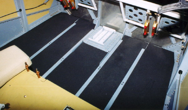
| Here you can see the black 3/4" sound proofing/insulation procured from Wick's. It's the same stuff I used in the floor in the baggage and seat areas. | |
 |
|
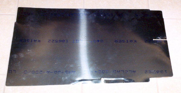
| This is one floor panel. It has been trimmed and bent to fit the sloping lower longerons on the fuselage sides. It is very difficult to get in and out which has to be done repeatedly during fitting. I would suggest making it in two pieces or cutting it several inches short of the firewall. | |
 |
|
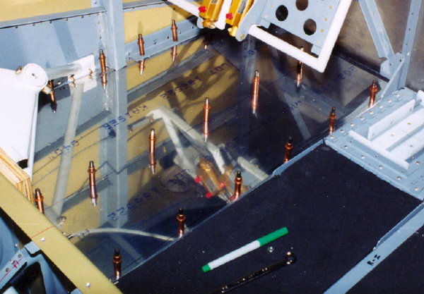
| With the panel in place, you can see how it has to on underneath the longeron in front of the bulkhead and on top of it aft of the bulkhead. I notched it out for the bulkhead and then joggled it a bit. | |
 |
|
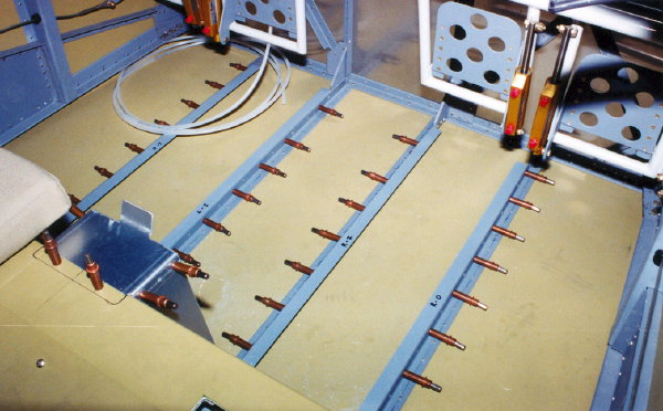
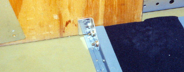
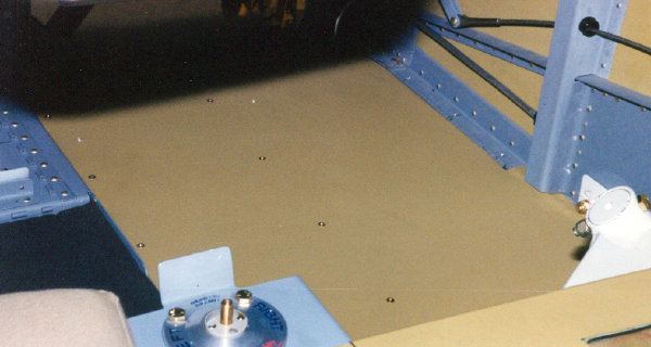
| Before finishing the floor, I thought it would be a good idea to make those little brackets that attach the floor stiffeners to the wing spar. | |
| A look at the floor and the fuel selector with its plumbing connected. | 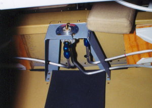 |
| Fuel lines snake around the left gear mount. | 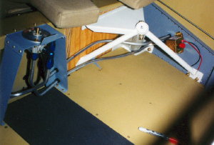 |
 |
With carpet across the floor, it should look good and I can use sheet metal screws to fasten it down to the floor to keep it in place as people get in and out. |
| Break lines behind the left rudder pedals at the firewall. There really isn't any reason to extend the floor in this area. | 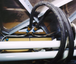 |