The Finish Kit (Page 2 of 3)
Journal Cover Page Page 1 Page 3
(To navigate the photo journal, click on the tabs on the right and the links at the top or bottom of this page.)
Empenage Fairing |
|
 |
|
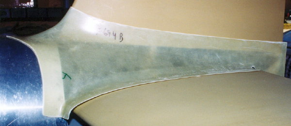
| Now for the Empenage fairing. Time to take my fiber glass skills to the next level. Here is what it looks like out of the box. Not too bad, but the leading edge over the horizontal stabilizer doesn't line up right and its going to need a little help to lay down nicely along the stabilizer skins. | |
 |
|
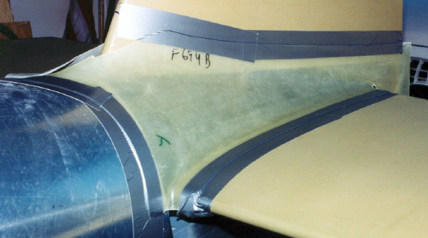
| Yikes! what a mess. But, don't worry. With a lot of time and hard work it can be rebuilt. I've cut the front section out so it will sit back on the leading edge of the horizontal stabilizer. I suppose the offending sections could be rebuilt instead, but this seemed like the thing to do at the time. The duct tape holds it in place for drilling to the skins. | |
| With clecoes through the drilled holes and release tape in place, its time to start rebuilding this thing. | 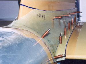 |
 |
|
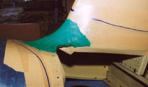
| Here is a side view of in the same state as above. | |
| As you can see, the two sides are completely split apart. | 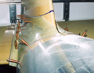 |
 |
Bridge of modeling clay. |
| Here is one of the layups. I know now that I should have taken great care to wipe up the running epoxy to save lots and lots of sanding and filing later. Getting the right amount of filler added helps too. | 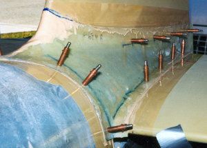 |
| After sanding one of the layups, its starting to fit nicely. But, there is still much work ahead. | 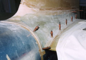 |
 |
|
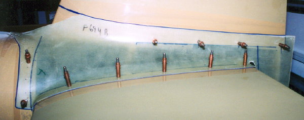
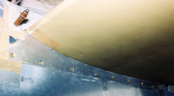
| Here is a shot of the aluminum fairing under the horizontal stabilizer. Also, you can see that the leading edge curve fits much better now. | |
 |
|
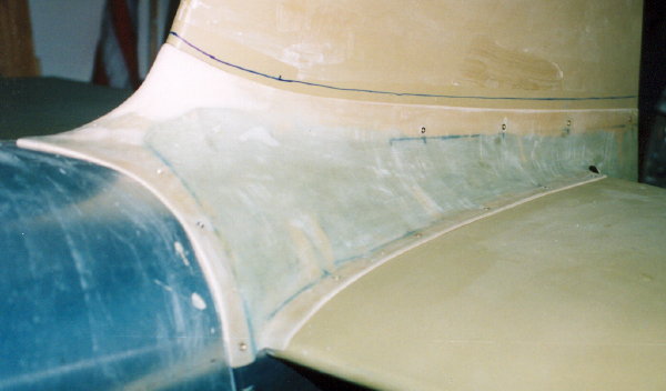
| A look from the right side looking forward. Another thing I would do differently is to coat a much larger section of the vertical stabilizer with release compound or release tape. The wet epoxy on the inside would difficult to keep off the stabilizer as it was placed back on the plane to set up. | |
 |
|
| I think its good enough. I lost count of the layups it took, but some probably could have been avoided with better care to the mixture and maybe using some fiber mat in areas that tended to run before they were set up. | |
 |
|
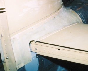
| Here is the final product with aft edge trimmed. Time to set it aside and wait until I forget how much work that was before doing any more glass parts. | |
|
|
 |
|
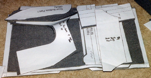
| This is the only part of the interior that I'll do for now. These are the seat backs. The pleats are made by sewing some upholstery foam to parts and then sewing them together. I used Van's seat cushion set and plans. On my set, the patter was 2" to thin. I found this out by making a set of dummy seat covers out of cheap canvas procured at Walmart. I used these in the plane for quite a while saving the finish fabric from a lot of wear. To fix the patter, I had to add 2" to the thickness of both the seat bottom and backs. | |
 |
|
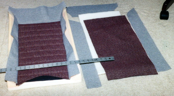
| A stack of parts cut out and stacked with their mating patter pieces. | |
 |
|
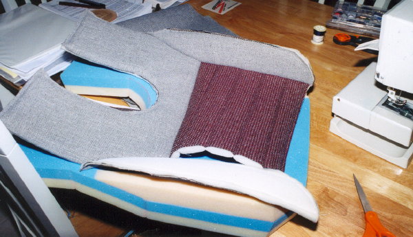
| Here is the seat bottoms on progress. All the sections on the top need to have the foam backing or they won't look right. It bothered me enough that I ripped it apart and started again. | |
| I'm pretty happy with the outcome. The recessed areas in the seat and back are glued down to the seat foam with 3M #77 spray adhesive. That hasn't worked as well as I hoped. I may come back to that after I get it flying. | 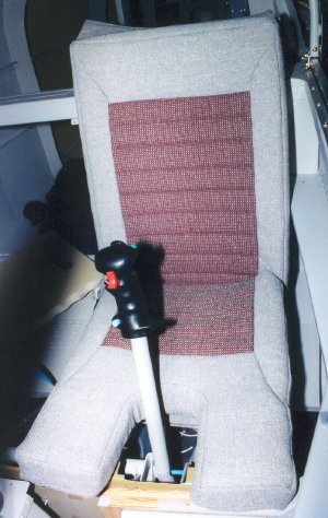 |
|
|
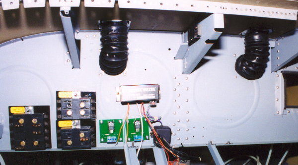
| As usual, it took me quit a while to figure out how to do this. I sure hope it works. The firewall is in the top of the picture. From the firewall, the heat tube goes through a rib and into a mixer. Once hot air is brought into the cabin with a valve on the front side of the firewall, it can be be directed to the floor or to the defrost vents in the glare shield or any combination of the two. In this picture the tube going to the floor heat is not connected to the mixer. The defrost side of the mixer is connected to a splitter and then two tubes take the heated air aft (up in this photo) through the instrument sub panel bulkhead. | 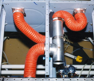 |
 |
|
| This photo shows the instrument sub panel from the aft side. Here you can see the black tubes that carry the heated air up to the glare shield. | |
| The heated tube exits out the top side of the glare shield. | 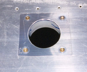 |
| I wanted to make the bracket removable from the top side. Now, I'm not sure why. This was my solution. I'm sure there are much better ways. Yes, the glare shield covering will cover the screws anyway. Next, I need some kind of diffuser, but that will have to wait. | 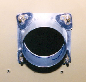 |