The Instrument Panel (Page 1 of 1)
Journal Cover Page
 |
|
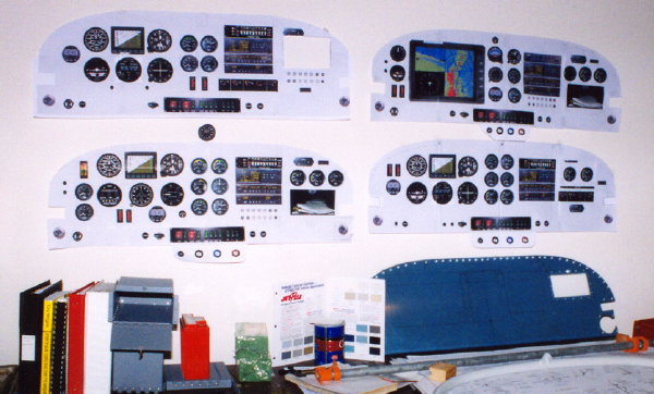
| I subscribe to the "stare at it until it looks right" school of design. The last four iterations of my panel design hang on a wall in a high traffic area of the house. When the desired changes reached the point that I could no longer visual how it would look, I would print a new full size version and hang it over the oldest one. | |
 |
|
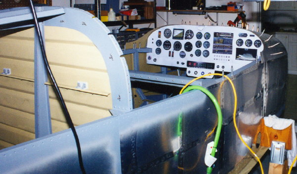
| Here is a mock up of one of the final designs in the fuselage. Fits very nicely. | |
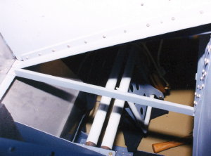
| In this shot, the supports that will hold the map box in place in the sub panel. Forward side of the sub panel is shown. | 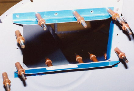 |
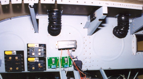
| This is the aft side of the sub panel. These four angles get riveted in place and a bit of foam weather stripping applied as a cushion. | 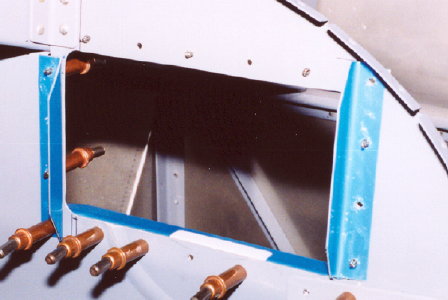 |
 |
|
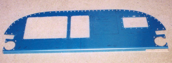
| This is the panel blank with some of the cut outs. The map box will go on the right. The large square cut outs are for sub panels. The one on the right is for the engine instruments and the one on the left is for the flight instruments. Also, shown are cut outs for the canopy decks on the lower sides and below those are cut outs for the cabin air vents. | |
 |
|
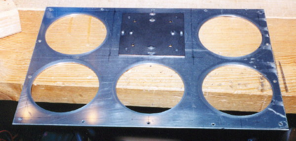
| This is the flight instrument sub panel with the instrument holes cut. The top middle hole is occupied by a jig helping me drill the instrument mounting screw holes. | |
 |
|
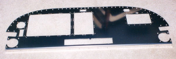
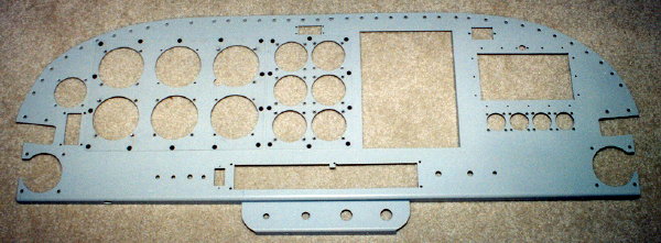
| Five more cut outs made in the main panel blank. On the right the rectangular one is for the Angle of Attack indicator and the round one is for the clock/timer. The top center square hole will hold the Emergency Locator Transmitter indicator and controls and the one above the map box is for the Hobbs hour meter. The long horizontal rectangular cut out in the bottom center is where the switches will go. | |
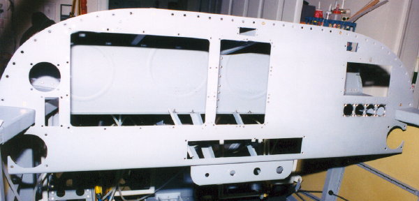
| With the panel blank in place, the bracing used for added rigidity are visible. Since the engine controls are at the bottom of the panel, it needed a lot of support in this area. Two of the braces have notches to clear the DC load center tray that holds the switches. | 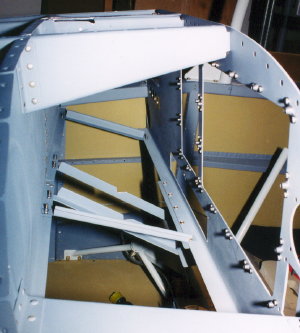 |
 |
Just needed one more brace shown here from the instrument sub panel to the firewall. |
 |
|
| In this shot, you can see four more little round holes below the map box cut out for the 1 1/4" UMA engine instruments. Also, bracket that will hold the engine controls is screwed onto the bottom at the center of the panel. | |
 |
|
| Here is a view of the sub panel looking forward. The auto style fuse blocks are on the right. The large is for the Auxiliary bus, the two smaller ones are for the main and auxiliary battery busses for the stuff that needs to have power even when the master switches are off. | |
 |
|
| Here is the instrument panel with all the holes cut and the sub panels attached. | |
 |
|
| Applying the final interior paint to the panel blank. With it in this position, you can see the hole on the bottom for the alternate static air valve. | |
 |
|
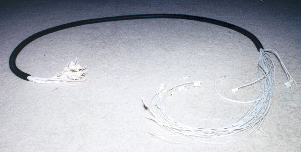
| This is the main wiring harness that will provide a secure path for all these wires go out from the instrument panel to various points aft of the wing spar. | |
 |
|
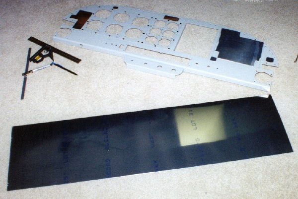
| It will never be more convenient to work on the instrument panel overlay. Better get started on it now. | |
 |
|
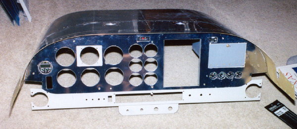
| A trial fit. Some of the instruments are already mounted in the panel to make sure everything lines up. | |
 |
|
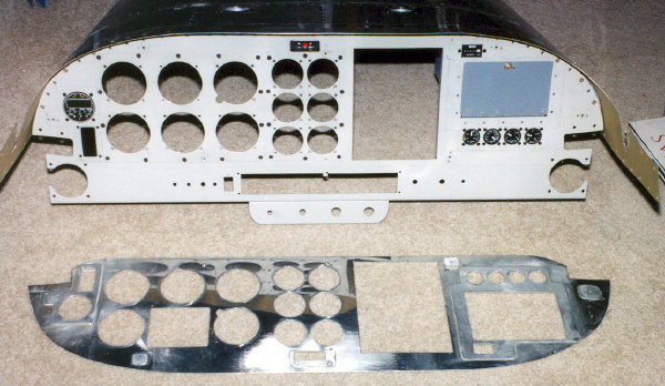
| If you look closely, you can see the shims I've applied to the backside of the panel overlay to bring it up even with the flight and engine instrument sub panels. | |
 |
|
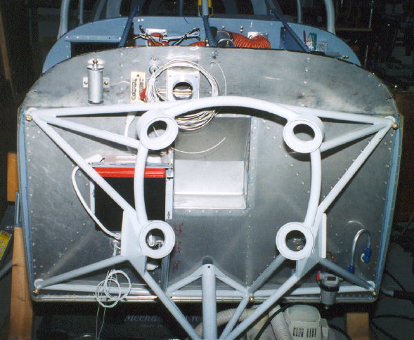
| Some of the wiring is starting to poke through the firewall. | |
 |
|
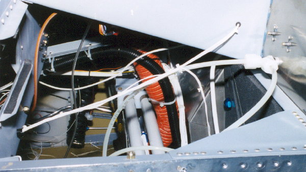
| This a view of the right side between the firewall and the instrument sub panel bulkhead. It's starting to get a little messy in there. | |
 |
|
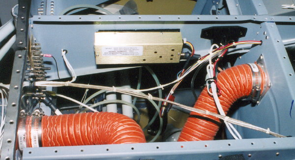
| This is the center bay between the firewall (on the left) and the instrument sub panel bulkhead. The gold box is the remotely mounted marker beacon receiver. Just to the right of it is the manifold pressure transducer. Wires seem to be going every which way. | |
| Looking down on the rudder pedal center mounting bracket, you can see the main batter and crossover contactors mounted to it. This location puts them close to the main battery. The auxiliary battery and starter contactors are mounted on the firewall on the engine side next to the axiliary battery. | 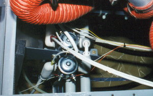 |
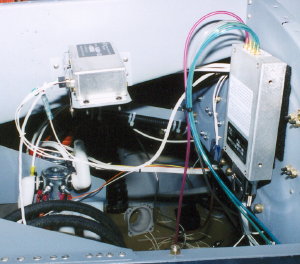 |
This is the left bay between the firewall (on the left) and the sub panel bulkhead. On the left is the remote compass module for the Dynon D10 EFIS. On the right is the AoA computer. The four plastic tubes are the differential static lines from the AoA ports and the pitot and static lines from the pitot tube. |
 |
|
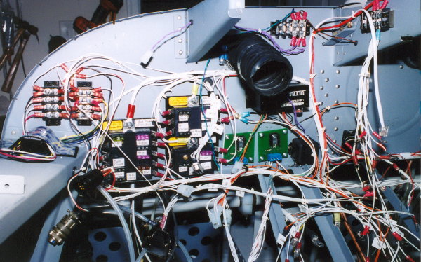
| This perspective is looking forward at the aft side of the instrument sub panel bulkhead. Most of the wiring in this area is complete at this point. From left to right, the elevator trim controller is strapped down to the canopy deck with velcro, two terminal blocks connecting the elevator trim wires, three fuse blocks for the battery and auxiliary busses, two dimmer circuit boards, two inverters for glareshield lighting and instrument back lighting, and two more terminal blocks used for instrument light connections. | |
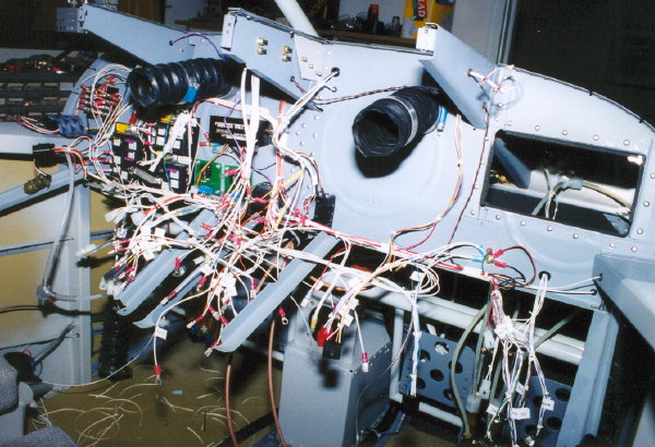
| Here is the plumbing exiting the wing root area forward of the wing spar. Its kind of a mess here because I wanted the interior tubes and wires to be hidden from sight. | 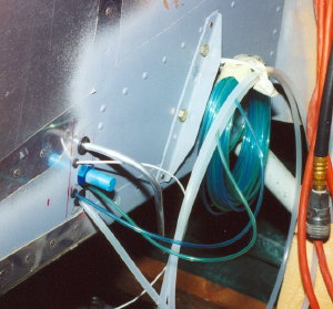 |
 |
|
| Another view of the instrument sub panel bulkhead. | |
|
|
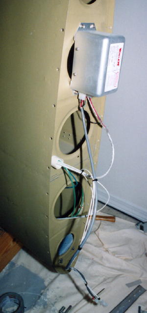 |
This photo shows how the strobe/nav light power supplies were mounted in the wing's most out board rib. Also, shown are the landing light wires going from the conduit to the landing lights in the out board wing bay and the green and blue plastic tubes that carry differential static pressure from the sensors back to the angle of attack computer. |
| At the other end of the conduit at the wing root, the lighting wires and static lines emerge. The static lines are routed through the wing spar so they can penetrate the fuselage skin out of site forward of the F602 bulkhead. | 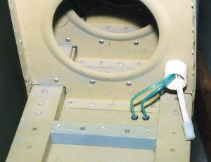 |
|
|
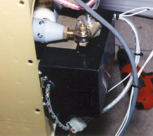 |
The black box is the auto pilot servo mounted to the most out board rib of the right wing. I made a push rod of the same materials/hardware used on the main push rods from the cabin area out to the aileron bell cranks. |
| The other end of the auto pilot servo push rod is attached to the aileron bell crank. Care must be taken to engineer correctly so that the range of travel meets installation requirements. | 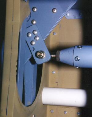 |
 |
|
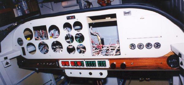
| Here the overlay is in place, but the flight instrument and engine instrument sub panels are missing. | |
 |
|
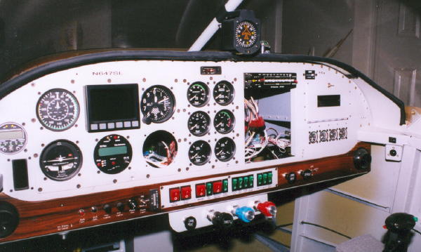
| View from the left of the flight and engine instrument sub panels, but without the overlay. Control cables are now installed. | |
 |
|
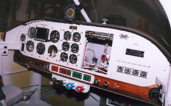
| View from the right. Only the audio panel is installed in the rectangular cut out for the radios. | |